DOF Reality M2 Kurulum Talimatları - Sayfa 12
Video Oyun Aksesuarları DOF Reality M2 için çevrimiçi göz atın veya pdf Kurulum Talimatları indirin. DOF Reality M2 15 sayfaları.
Ayrıca DOF Reality M2 için: Kurulum Talimatları (14 sayfalar)

Setup Instructions DOF Reality M2
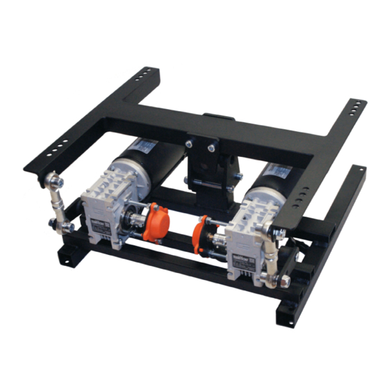
5.3 Motor arm is not horizontal in the neutral position
The resting position of the black motor arm should be:
If your motor arm is out of the natural/level position it should be reset. Correct calibration is the
default resting arm position of the motor. Setting this correctly fixes many problems commonly
experienced by users. To recalibrate the motor arm, you will need the small "allen wrench" or
"hex key" provided in your hardware kit.
Over time the motor-sensor coupler bolts may become loose and the "neutral" motor position can get
misaligned from normal (often the arm moves just a bit higher than horizontal). If this is the case perform
tests (see section 5.4) to make sure motor is moving correctly first or consult DOF Reality support.
Please review the video of the calibration procedure:
https://www.youtube.com/watch?v=Wa6hRdMB4vA
1. Before starting, close all applications possible PC, especially SimRacingStudio and SimHub
(check the Windows task manager to make sure).
2. Download http://dofreality.com/SMC3Utils.zip, unzip all contents into any local folder on your
PC. Open with notepad file SMC3Utils.ini and set COMM_PORT= to correct COM port number
from your Windows Device Manager (see 5.1). If you have H6/P6 DOF: each control box has a
specific port number. For SRS to find the control box, you must know which box corresponds to
the desired control box. See section 5.2.4.Run SMC3Utils.exe. If you are getting an error
messages about COM port communication, you haven't set port the number properly in this
step.
3. Make sure the DOFR control box power is OFF (make sure motor connections and the USB
remain fully plugged in).
4. Using a wrench and the large allen key, disconnect the silver threaded "motor arm" from the
motor that needs to be re-calibrated only from motor side and leave hanging freely. If you have
a damper attached, you will need to disconnect that as well. The motor needs to be free to
move.
5. On the side of the motor pointing towards the center of the platform, use a small allen key to
loosen the "coupler" (silver tube like roller). You only want to loosen the two small allen screws
on the MOTOR SIDE the other side is the "sensor" that connects to the plastic cover. Do not
touch the sensor side allen screws.
6. On your PC go to the SMC3 application.
7. With a computer screen-shot (or your phone) take a picture of the SMC3 screen with the
current settings and values (IMPORTANT). The default settings are: Fpid / 10, Kp = 120, Ki = 1,
Kd = 10, Ks = 5, PWMmin = 0, PWMmax = 180, PWMrev =200, Max limit = 50, Clip Input = 190,
Deadzone = 0.
8. At top left of SMC3 tool now click "ON" the motor that needs calibrated.
9. Click the "step 1" buttons to say "step 10"
10. Click "KP" down to "60"
11. "PWMmax" to "60" and "Ki" to "0" (zero).
12. At this point the "Max Limits" and "Clip Input" should also have adjusted down to 0 as well.
If not, then click them both to "0".
13. Power ON the DOFR control box.
12
