ASL INTERCOM BS 216 Посібник користувача - Сторінка 5
Переглянути онлайн або завантажити pdf Посібник користувача для Домофонна система ASL INTERCOM BS 216. ASL INTERCOM BS 216 9 сторінок. Dual channel master station
Також для ASL INTERCOM BS 216: Посібник користувача (11 сторінок), Короткий посібник (4 сторінок)
7.0
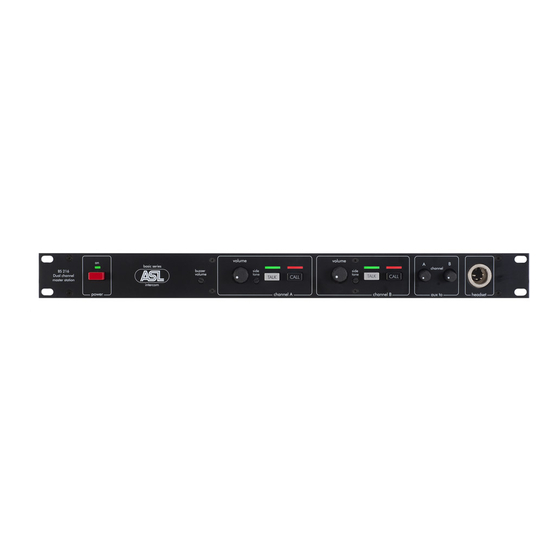
FRONT PANEL CONTROLS & CONNECTOR
1
POWER ON/OFF switch
Mains power push button for switching ON and OFF
the internal power supply.
2
MAINS POWER LED
This LED illuminates if line power is supplied by the
internal power supply.
3A
BUZZER VOLUME trimmer
This trimmer adjusts the volume of the buzzer.
3B
BUZZER
This buzzer indicates an incoming or outgoing call. It
is activated by pushing a CALL button on this station
or a CALL button on any other station for longer
than two seconds.
The volume of the buzzer may be adjusted with the
buzzer volume control.
4
VOLUME A & B control knobs
These knobs adjust the listen level for the headset.
Each channel has to be adjusted separately.
5
SIDE TONE trimmers
These trimmers adjust the level of one‟s voice as
heard in one‟s headset.
Adjustment procedure (for each channel separately):
set the trimmer in start position: fully
clockwise
switch off the microphones of all connected
stations
push the TALK button of the channel
turn up the volume of the channel
speak into the headset microphone
adjust the listen level by turning the side
tone trimmer of the channel.
PAGE 5
User Manual BS 216 / Issue 2011 © ASL Intercom BV
The trimmer operating area is between fully
clockwise and minimum level. Adjusting the side
tone does not affect the level of your voice as heard
by other stations.
TALK A & B buttons + LED's
6
These buttons allows the user to talk to each
channel separately or to both channels
simultaneously. The large green LED‟s indicate if
the talk function is activated.
CALL A & B buttons + LED's
7
A Call button activates the Call system.
By a momentary push a Call signal is sent to all
stations connected to the referring intercom channel.
The Call LED on this station and on all to the
channel connected stations starts flashing. Pushing
and holding a Call button for 2 seconds activates the
call buzzer in all stations. After the CALL button is
released the Call LED‟s continue to flash for a
further 2 seconds.
8
AUX VOLUME controls A & B
These knobs adjust the level of the Aux input signal
to each of the two intercom lines.
9
HEADSET connector
A XLR-4 type connector to connect a headset. The
can impedance must be minimum 200 ohms. The
headset microphone may be of the dynamic or
electret type.
Pin assignments:
Pin 1:
shield mic. (GND)
Pin 2:
mic. +
Pin 3:
phones +
phones –
Pin 4: