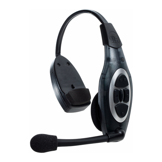
3M XT-1 Технічний бюлетень - Сторінка 4
Переглянути онлайн або завантажити pdf Технічний бюлетень для Гарнітури 3M XT-1. 3M XT-1 10 сторінок. Drive-thru systems
Також для 3M XT-1: Короткий довідник (6 сторінок), Короткий довідник (2 сторінок), Технічні дані (2 сторінок), Технічний бюлетень (2 сторінок), Посібник із швидкого старту (3 сторінок), Посібник (8 сторінок)

Replacing Boom Microphone Assembly
Tools Required:
1 - Small size Phillips screwdriver
1 - External retaining ring removal tool
3M OEM Parts and SKUs:
Procedure:
1. Repeat steps 1-4 from the previous procedure Replacing Inner Case Assembly.
2. Disconnect Microphone Boom Assembly wires by pulling the connector off
the main circuit board. See Fig 8.
3. Locate and remove the retaining ring using the retaining ring tool. See illustration.
Important Note:
Make sure you set the retaining ring tool adjustment screw to
limit how far the retaining ring is expanded. Unless this is done,
the retaining ring will stretch out of shape to a point where it will
not stay in its groove.
4. Remove the clip, nylon washer and boom microphone assembly.
5. Install replacement boom microphone by performing steps 1-3 in reverse order.
6. Reinstall the battery and check operation of the headset prior to
returning it to regular operation.
Replacing Outer Case Assembly
Tools Required:
1 - Small size Phillips screwdriver
3M OEM Parts and SKUs:
Procedure:
1. Replace the Outer Case Assembly as follows:
a. Remove the boom microphone assembly as described in the previous
procedure and install it in the new replacement outer case.
b. Connect the connector on the boom microphone wires to the
connector on the main circuit board.
c. Reassemble the inner and outer case halves by bringing the two halves
together and replace the screws as shown in Fig 9.
2. Make sure the LED Lens is still in place. Otherwise, follow the procedure
Replacing the Indicator LED Lens to re-install the LED Lens.
3. Reinstall the battery (Fig 10) and check operation of the headset prior to
returning it to regular operation.
FIGURE 8
Retaining Ring
Clip
Nylon Washer
Boom Microphone Assembly
FIGURE 9
PC Board
Microphone
Assembly Connector
FIGURE 10
