Academy Audio Hi-End MUSES VCM Посібник користувача - Сторінка 4
Переглянути онлайн або завантажити pdf Посібник користувача для Блок управління Academy Audio Hi-End MUSES VCM. Academy Audio Hi-End MUSES VCM 12 сторінок. Mini electronic volume controls

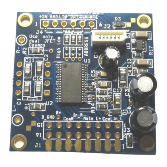
A universal connector J3 combines all audio, power and control connection points. J3 is arranged as a
16-pin dual row 0.100"x0.100" PCB pattern that can accept a standard straight or right angle header.
With a header installed, the connector J3 may be used as a mechanical mounting feature for the VCM
board. The J3 connector pin assignment is summarized in a Table 1.
Table 1. J3 Pin Assignment
Pin
1
+15V
3
GND
5
-15V
8
MUTE
9
CLOCK
11
LATCH
13
DATA
16
D_GND
2
In_L
4
Com_L
6
L+
7
Out_L
10
In_R
12
Com_R
14
R+
15
Out_R
* Control signal connections may be used as input or output depending on the application.
A control connector J4 is provided for connection with an optional matching MCU-M control board. The
J4 connector pin assignment is summarized in a Table 2.
Table 2. J2 and J4 Pin Assignment
Pin
1
+5V
2
D_GND
6
LATCH
7
DATA
5
CLOCK
8
MUTE
If an MCU Control Board or a remotely installed MCU-M control board is used, all control signals are
provided through the flat cable connector J2.
Ref
+12V to +15V analog power
Analog Ground
-12V to -15V analog power
Output to Muting relay control. (Active High – Mute Off.)
Not Used
Not Used
Not Used
Digital Ground
Left Channel Input
Left Channel Common
Left Channel Potentiometer Output
Left Channel Opamp Output (with opamp installed)
Right Channel Input
Right Channel Common
Right Channel Potentiometer Output
Right Channel Opamp Output (with opamp installed)
Ref
Digital Power for MCU-M controller only
Digital Ground
LATCH MUSES Control Signal
DATA MUSES Control Signal
CLOCK MUSES Control Signal
Mute Control Input. (Active High – Mute Off.)
Page 4 of 11
Description
Power
Control*
Audio
Description
