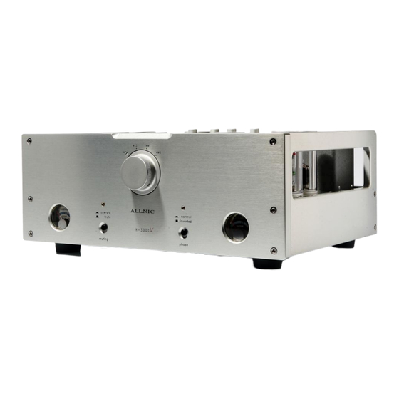
ALLNIC AUDIO H-3000V Посібник користувача - Сторінка 7
Переглянути онлайн або завантажити pdf Посібник користувача для Підсилювач ALLNIC AUDIO H-3000V. ALLNIC AUDIO H-3000V 15 сторінок. Phono stage
Також для ALLNIC AUDIO H-3000V: Посібник користувача (15 сторінок), Посібник користувача (15 сторінок)

The H-3000V power supply you have purchased is set
internally for AC 110/120 volt – 60 HZ operation. There
is no way to change this to another AC setting without
return of the unit to the factory for re-wiring, at the
owner's cost, including transport both directions.
C.
INPUTS
There are two (2) sets of two (2) pairs of single-ended (RCA)
inputs. These two pairs are located in the middle of the rear
of the phono stage (See Figure 1) and labeled "input" in the
middle above them. Each channel pair of inputs is aligned
vertically, with the left channel input at the top and the right
channel input on the bottom. The two left hand pairs of
inputs (facing the back of the phono stage) have an "MC"
label above the two left channel connectors; these are the
two input pairs for a moving coil cartridge. The right hand
pair of inputs has an "MM" label above the left channel
connectors; these are the two input pairs for a moving
magnet cartridge. Each pair of moving coil and moving
magnet connections has a number label between the left and
right channel input connections.
In each case, for both MC and MM connections, the left hand
vertically aligned pair of connections (again, facing the back
of the unit) corresponds to input 1 for the selector knob on
the front panel of the phono stage , while the right hand
vertically aligned pair is input 2.
Between the two sets of MC and MM input connections is
a screw type ground connection pin.
When you are facing the front of the H-3000V, the two pairs
of MC connections are on the right/centre of the unit, with
the two MM connections immediately to their left on the
other side of the ground connection.
The H-3000V has been designed and manufactured to work
most synergistically with Allnic Audio preamplifiers, pre-
phono stages and equalization products.
D.
OUTPUTS
The H-3000V is equipped with one pair of unbalanced or
"single-ended" (RCA) outputs and one pair of true balanced
(XLR) output connections. The left channel output
connections are labeled "left output" and are just to the left
of the DC Source Input. The right channel output connections
are labeled "right output" and are on the far left hand side of the
rear of the phono stage unit (See Figure 1). In each pair, the
balanced (XLR) connection is labeled "1", and the unbalanced
(RCA) connection is labeled "2".
Above each pair of outputs, comprised of one single-
-ended (RCA) connection and one balanced (XLR)
connection, is a switch for selecting either the balanced or
the single-ended connector. The switches are labeled
"unbalanced output". Moving the unbalanced output
switches to the right (facing the rear of the unity) sets the
outputs to their respective unbalanced (RCA) connector.
Of course, the opposite position in each case sets the
switches for the balanced connectors. Be sure to have
both switches set for the connection you are using. You
may have both balanced and unbalanced outputs
connected at the same time without introducing hum
PROVIDED you have the output switches set to unbalanced
output.
E.
Moving Coil (MC) Transformer Controls
On the top of each channel's MC transformer on the
centre rear of the chassis deck of the phono stage unit,
there is a rotating control. Turn the control knobs to select
from four (+22, +26, +28, +32dB) gain factors. The four
control positions are labeled as both gain and the turn
ratio of the MC transformer; for example, the lowest gain
position of +22dB automatically corresponds to a turn
ratio of x13 (see Figure 3). You should use identical
settings for both transformers to avoid channel imbalance.
NOTE:
Please mute your H-3000V, and/or reduce your
preamplifier's volume control, during transformer gain
adjustments. Be aware if you are increasing gain, that you
may hit an uncomfortably loud volume level.
F.
IMPEDANCE CONTROL
The Impedance control is located at the rear of the top
plate of the H-3000V chassis (see Figure 6). It has four
positions, 10, 20, 30 and 47 KΩ (thousand ohms). Use the
impedance control to match the H-3000 to the impedance
of your cartridges. For MM cartridges always set the
control at 47 KΩ. Vary the impedance settings to match
your MC cartridges. By experimenting with the impedance
settings and the transformer controls together, you can
obtain optimum performance from your MC cartridges.
7
