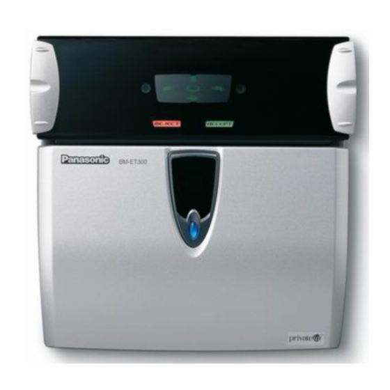
Panasonic BM-ET300AE Інструкція з експлуатації Посібник з експлуатації - Сторінка 13
Переглянути онлайн або завантажити pdf Інструкція з експлуатації Посібник з експлуатації для Цифрова камера Panasonic BM-ET300AE. Panasonic BM-ET300AE 35 сторінок. Iris camera

● Connection terminal
Not in use
Not in use
q Wiegand power (card reader)
Supplies power to a card reader.
w Wiegand GND (card reader)
This is the ground terminal for the power supply and
communication between the iris camera and a card
reader.
e Wiegand DATA0 (card reader)
A signal (DATA0) is input from a card reader to this ter-
minal.
r Wiegand DATA1 (card reader)
A signal (DATA1) is input from a card reader to this ter-
minal.
y Wiegand power (access control panel)
The iris camera works even when nothing is connected
to this terminal.
u Wiegand GND (access control panel)
This is the ground terminal for communication between
the iris camera and an access control panel.
i Wiegand DATA0 (access control panel)
A signal (DATA0) is output from this terminal to an
access control panel.
o Wiegand DATA1 (access control panel)
A signal (DATA1) is output from this terminal to an
access control panel.
@1
Pin No.
q
w
e
r
t
y
u
i
o
!0
Note: Do not connect any cables
to connectors "Not in use".
It may cause malfunction.
!1
!2
!3
Not in use
!4
!5
!6
!7
!8
!9
@0
!6 Recognition result output1 (ACCEPT)
This terminal is activated when recognition is success-
fully completed.
!7 Recognition result output2 (REJECT)
This terminal is activated when recognition is not suc-
cessfully completed.
!8 Alarm output1 (power status)
This terminal is closed and low when power is supplied
from an external power-supply device to the iris cam-
era. The terminal is opened when the power supply is
shut down.
!9 Alarm output2 (tamper detection)
This terminal is activated when the iris camera enters
the "tamper detection" mode by the front/rear tamper
detection switch (activated until the "tamper detection"
mode is cancelled).
@0 GND
This is the common terminal for the alarm output con-
nectors.
@1 Power input terminals
12 V DC (+12 V at the left/GND at the right) or 24 V AC
13
