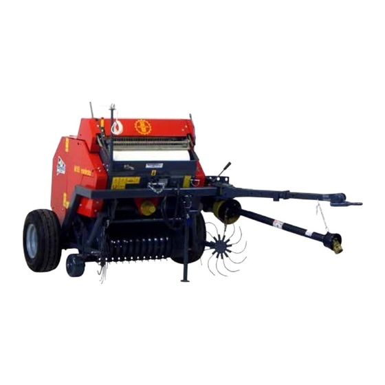
Abbriata Miniroto M50 Посібник із швидкого старту - Сторінка 2
Переглянути онлайн або завантажити pdf Посібник із швидкого старту для Сільськогосподарське обладнання Abbriata Miniroto M50. Abbriata Miniroto M50 19 сторінок.

Abbriata M50 Quick Start Guide
Contents
Scope and Purpose .............................................................................................................................................. 3
Cutting the driveline to fit your tractor ............................................................................................................... 3
Read the owner's manual .................................................................................................................................... 3
Unloading from the truck .................................................................................................................................... 3
Removing Center Draw type from pallet ............................................................................................................ 3
Hitch pin for pintle hitch ................................................................................................................................. 6
Remove boards from pallet ............................................................................................................................. 7
Measure tractor hitch height ............................................................................................................................... 9
Setting hitch height ........................................................................................................................................... 10
Gathering wheels .............................................................................................................................................. 11
Pickup height setting ......................................................................................................................................... 12
Gauge wheel...................................................................................................................................................... 13
Height verification ............................................................................................................................................ 13
Bale sensor and siren ........................................................................................................................................ 14
Bale density ....................................................................................................................................................... 14
Shear pin ........................................................................................................................................................... 15
Bag of spares ..................................................................................................................................................... 15
Bale ejector plates ............................................................................................................................................. 16
Lift points .......................................................................................................................................................... 17
Oil the chains .................................................................................................................................................... 17
Door speed control ............................................................................................................................................ 18
Figure 1 fork form this side if possible ................................................................................................................... 3
Figure 2 center draw type are attached to the pallet with the draw bar folded up for shipping .............................. 4
Figure 3 leave the steel strapping in place .............................................................................................................. 4
Figure 4 bolts that hold drawbar angle adjustment use 24 mm socket ................................................................... 5
Figure 5 cut steel strap holding the draw bar down ............................................................................................... 5
Figure 6 raising up the drawbar .............................................................................................................................. 5
Figure 7 draw bar folded down .............................................................................................................................. 6
Figure 8 hitch pin parts assembled......................................................................................................................... 6
Figure 9 hitch to baler ............................................................................................................................................ 7
Figure 10 remove block in center .......................................................................................................................... 7
Figure 11 remove boards from jack stand.............................................................................................................. 8
