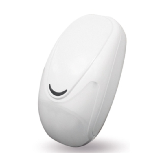
AMC SMILE 16/P Schnellstart-Handbuch - Seite 2
Blättern Sie online oder laden Sie pdf Schnellstart-Handbuch für Sicherheitssensoren AMC SMILE 16/P herunter. AMC SMILE 16/P 4 Seiten. Digital pir detector pet immune

true motion from any other disturbances causing false alarms. It features a regulator to adjust its range from
3 m to 18 m and a double-impulse event counter with a time window of 5 sec., selectable in installations
where an improved protection against false alarms is required. The housing does not require any screws
neither to fasten the electronic board to the base nor to open the detector. To disassemble the detector just
press the tooth on the bottom of the case (see figure) and pull out the PCB by pushing the clip and by lever-
ing on the ABS supports (see figure). In this way it will be possible to freely work on the PCB. Thanks to the
terminal BLOCK SENSOR (B/S) it is possible to activate and disable the Walk Test LED without opening
the housing.
2. INSTALLATION PROCEDURE
- By using a thin screwdriver, push the round tooth on the bottom (see figure 1) and open the housing
- Remove the PCB from the base (figure)
- Use a screwdriver to pierce the knockouts on the side of the base where you wish to attach the detector to
the wall or use the optional swivel bracket. (height)
- Route the wires via the rear channel into the base and let them pass through the hole on the top of the
housing (see figure)
- Wire up the terminals following the connections shown in figure 3.
CAUTION: Do not partially or totally obscure the field of view of the detector
3. CONNECTIONS AND SETTINGS
As for the connections with the control unit please refer to figure 3.
- To disable the LED WALK TEST you have to apply a voltage of +13,8 VDC at terminal B/S, while if you
want to disable it only when the control unit is disarmed connect a plus voltage only when the system is
disarmed. If the control unit does not have a plus voltage command, but a ground voltage command, con-
nect the terminal B/S to both the power supply plus, through a 1 KΩ resistor, and to a system status open
collector output (ground voltage output) of the control unit (see figure 3)
- With JUMPER 1 it is possible to determine if the detector trigger an alarm after 1 or 2 consecutive motions
(JP1 OPEN = 1 impulse, CLOSED = 2 impulses within 5 sec.)
- It is possible to adjust the coverage within the range 3 m to 18 m. In an usual residential premise it is sug-
gested to regulate the trimmer at half its range.
FRANÇAIS
1. INTRODUCTION
Le SMILE 16 est un détecteur infrarouge digital avec animaux immunisés jusqu'à 10 kg . Grâce à l'innovant
système d'acquisition et de traitement numérique du signal (AMC DMS - Digital Modulation System) du
détecteur pyroélectrique (2 éléments), une portée de 18m et un angle de couverture de 90° garantissent
une protection optimale contre les déclenchements intempestifs.
Le SMILE 16 est équipé d'un régulateur de portée avec lequel il est possible de règler la sensibilité de 3 à
18 m et d'un comptage d'impulsion avec une fenêtre de temps de 5" activable dans les cas où est requise
une haute protection contre les déclenchements intempestifs.
La conception mécanique a été réalisée de telle façon à ne pas utiliser de vis pour la fixation de la platine
électronique à l'intérieur du détecteur et pour l'ouverture du capot du SMILE 16.
2 INSTALLATION
Pour l'installation, ouvrir le détecteur en pressant sur le petit clip se trouvant dans la partie inférieure à l'aide
d'un petit tournevis (voir fig1) puis déclipser la platine électronique (voir fig 2).
Défoncer les pré-percements ou utiliser une rotule suivant le type d'installation puis faire sortir le cable de
raccordement dans la partie supérieure et fixer le fond.
ATTENTION: Ne pas occulter partiellement ou totalement le champ de vision du détecteur.
3 CABLAGE ET REGLAGE
Cabler le détecteur en respectant la polarité (voir fig 3).
Il est possible de désactiver la LED de test en activant l'entrée B/S par une tension (voir fig 3).
Sélection du comptage d'impulsion grâce au jumper JP1(voir fig 4) Ouvert = 1 impulsion; Fermé = 2 impul-
sions de 5". Pour le réglage de la portée de l'infrarouge de 3 m à 18 m, procéder comme suit :
- Mettre le potentiomètre "COVERAGE" au minimum (sens anti horaire) puis augmenter celui-ci (sens horai-
re) pas à pas afin d'obtenir la portée desirée.
www.amcelettronica.com
SMILE 16 Digital Pir Detector
1
Installation Instructions v1.1
