Flomatic DHC-100D Konfigurations- und Betriebshandbuch - Seite 4
Blättern Sie online oder laden Sie pdf Konfigurations- und Betriebshandbuch für Controller Flomatic DHC-100D herunter. Flomatic DHC-100D 15 Seiten. Digital high-resolution controller
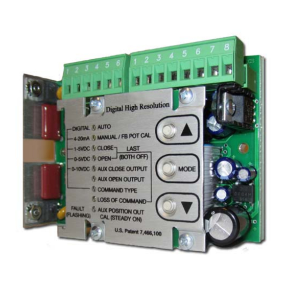
Flomatic Smart Card
Model FDHC-100 (Digital High-Resolution Controller)
Configuration and Operation Manual
and open positions need to be set and the unit automatically and continuously sets all other
parameters when placed in the AUTO mode.
CAUTION! These units are intended to be mounted in an appropriate enclosure to avoid electrical
shocks and exposure to electrostatic charges. High voltages are present on the outside of the unit when
power is applied. AC power should be disconnected and antistatic measures should be taken prior to any
wiring of these units. A heater and thermostat should be used where condensation may occur.
POWER / SIGNAL (J2)
Power is connected to pins 1, 2, and 3 as shown in the block diagram. The fuse installed on the unit is
rated for maximum output current that can be safely delivered by the AC outputs. Replacement fuses
must not exceed the maximum rating to prevent damage to the unit. Smaller fuse sizes can be used
with smaller motors – consult the actuator manufacturer for appropriate fuse size and type. An
appropriate command signal, either 0-5V, 0-10V, 1-5V, or 4-20mA, should be connected to pin 5 or 6
(As shown in the Block Diagram) while using pin 4 as the return
configured for the type of command signal that is to be used (see COMMAND TYPE). Pin 7 of J2
provides an auxiliary +5 V output which can be used to connect a command potentiometer. By
connecting one end of a potentiometer to pin 7, the other end to pin 4, and the wiper to pin 6, a local
control knob can be implemented. Pin 8 provides an auxiliary + 15VDC output which can be used to
power an input or output 4-20mA transmitter.
ACTUATOR (J1)
The actuator motor and feedback potentiometer are connected to J1 as shown in the Block Diagram. The
Motor Neutral wire must be connected to pin 2, while one motor winding is connected to pin 1 and the
other winding to pin 3. The feedback potentiometer wiper must be connected to pin 5, while one end is
connected to pin 4 and the other end to pin 6. The Polarity Detection feature of the FDHC-100
automatically determines which motor winding to control based on where the
are set; this feature also eliminates the need to rewire the unit for direct or reverse acting applications.
When the (▲) and (▼) buttons are used to control the actuator, the (▲) button will turn on the motor
winding connected to pin 1, while the (▼) button will turn on the motor winding connected to pin 3. See
MANUAL/FB POT CAL for more details.
OVERRIDE (J7)
J7 provides a simple 2-wire connection that can override the FDHC-100 to perform a variety of external
control functions. Using an appropriate interface module, commonly used auto/manual station switches
are easily implemented with low voltage/low current switches. See Special Applications for more details.
The factory installed jumper between pins 1 and 2 enables normal opera operation of the FDHC-100 and
must be installed if the external override functions are not used.
MODE
The MODE button is used to select the desired function of operation. When the MODE button is pressed,
the unit will switch to the next function and the appropriate LED indicator will turn on to let the user
know which function is selected. Except for the MANUAL/FB POT CAL mode, the associated mode
indicator will be steady on; for some of the modes other indicators will flash to indicate specific settings
associated with the mode. Each of the modes is described in more detail in the following sections. If a
0-5V or 0-10V command signal is used, the LOSS OF COMMAND function cannot be used. The MODE
Flomatic Corporation
Glens Falls, NY 12801
Phone (518) 761-9797
Fax (518) 761-9798
TM
FDHC-100 Configuration & Operation Man. Rev 0
August 16, 2010
signal ground
4 of 14
. The FDHC-100 must be
open
closed
and
positions