CO2 Meter Gastrack GAP-100 Schnellstart-Handbuch
Blättern Sie online oder laden Sie pdf Schnellstart-Handbuch für Messgeräte CO2 Meter Gastrack GAP-100 herunter. CO2 Meter Gastrack GAP-100 2 Seiten. Gas analyzer probe
Q U I C K S TAR T G U I D E
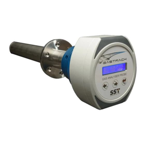
Gastrack
Gas Analyzer Probe (GAP-100)
1a.
Unpack the gas analyzer probe, accessories and
documents. Ensure contents are correct, contact CO2Meter, if
anything is missing.
1b.
Transfer the device to a clean workbench.
NOTE:
Read the User Guide BEFORE proceeding; the Quick Start
Guide (this document) is for reference only.
2.
If required, remove the head housing (1) from the probe
body (2):
•
Using a 10mm socket (or spanner), loosen clamp (3).
•
Carefully withdraw the probe body from the head housing.
1
3
3.
Measure the distance between the probe installation site
and the controller, and cut cable to length.
NOTE:
Leave enough cable length to ensure the probe can be
removed from its location without stretching the cable.
CAUTION:
Cable MUST be shielded.
4.
Remove the front panel (1) and set to one side:
•
Loosen four captive screws (2) and carefully ease the
front panel (1) from the housing.
•
Disconnect the ribbon cable from the front panel (1).
WARNING:
Shock hazard, do NOT apply power!
5a.
Prepare your cable; shielding exposed and wire ends
trimmed.
5b.
Feed cable through the gland and wire connector.
CAUTION:
Make sure the terminals are wired as shown;
failure to connect power correctly could result in irreversible
product damage that is NOT covered by warranty.
Power Supply
2
PIN 1:
PIN 2:
Digital Output
PIN 3:
PIN 4:
Analogue Output
PIN 5:
PIN 6:
PIN 7:
Relay Output
PIN 8:
PIN 9:
PIN 10:
PIN 11:
NOTE:
Do NOT leave any wires loose; accidental
shorting may cause product damage.
5c.
Carefully pull cable back through the gland until the
connector aligns with the board; fit connector to the board.
2
CAUTION:
positioned to ensure the device is grounded properly.
1
5d.
Using a 20mm spanner, tighten the cable gland to secure
the cable in place.
NOTE:
the gland.
2
6.
Fit the front panel and screw covers to the probe:
•
•
24V
DC
•
0V
COM1
COM2
Analogue GND
Analogue Out1
Analogue Out2
Relay 1 In
Relay 1 Out
Relay 2 In
Relay 2 Out
Always handle the interface board using the correct
ESD handling precautions.
Make sure the shielding is intact and correctly
Be careful not to over-tension the wires or over-tighten
Connect the ribbon cable to the front panel.
Install the front panel (1) to the head housing and
secure in place with the four captive screws (2).
Fit the screw covers (3).
2
1
3
Next