CO2 Meter RAD-0002 Betriebshandbuch
Blättern Sie online oder laden Sie pdf Betriebshandbuch für Monitor CO2 Meter RAD-0002 herunter. CO2 Meter RAD-0002 2 Seiten. Oxygen monitor, remote oxygen storage safety system
Auch für CO2 Meter RAD-0002: Betriebshandbuch (14 seiten)
Oxygen Monitor Operating Manual
Model: RAD-0002 Remote Oxygen Storage Safety System
1. Product Description
Thank you for selecting the RAD-0002 Remote Oxygen Storage Safety System.
This monitor is designed to detect oxygen depletion in enclosed spaces and to
warn occupants of low oxygen levels. Low concentrations of oxygen (O2) in
confined spaces are dangerous, and may lead to health problems ranging from
headaches and fatigue to asphyxiation and death. This monitor has both audible
and visual alarms which activate when the O2 concentration is lower than the
pre-set alarm levels. Detection of low levels of O2 will also activate relays that can
be used for a fan or air-handling system to ventilate the confined space and
improve O2 concentration in the area.
The RAD-0002 O2 Monitor is cost-effective and has many features including:
1. Separate SEU (Main Sensor Unit) and RDU (Remote Display Unit) allow you to
see warning before entering an enclosed area. Up to 3 RDUs can be used.
2. Large digital LCD display clearly indicates the ambient O2 concentration.
3. Relay outputs to control ventilation devices.
4. Audible and visual alarm indications at three separate alarm levels. Ability to
add strobes for additional indication.
5. Automatic barometric pressure compensation for high altitude use.
2. Package Contents & Description
The RAD-0002 package comprises the following parts:
SEU (Main Sensor Unit), RDU (Remote Display Unit), Power Supply (Pre-Wired),
CAT 5 Communication Cable (1 piece), Relay Cables (3 pieces),
Wall Plug Safety Strap (1 piece), Warning Signs, User Manual (1 piece)
Mounting Brackets (2 pieces), Screws (13 pieces), Wall Anchors (12 pieces)
Cable Clips (10 pieces), International Power Adaptor (3 pieces)
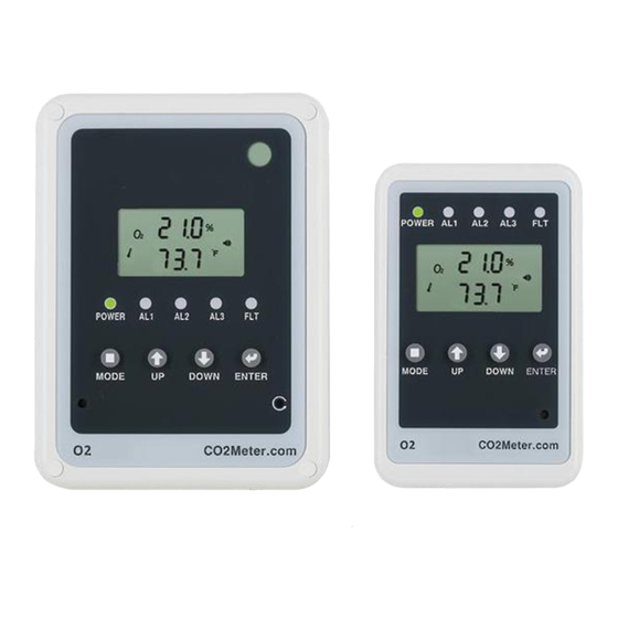
SEU (Main Sensor Unit)
A. O2 Sensor
B. LCD display
C. Power Green LED
D. Alarm 1 Red LED
E. Alarm 2 Red LED
F. Alarm 3 Red LED
G. Fault Yellow LED
H. MODE Button
I. UP Button
L. Alarm Buzzer
J. DOWN Button
K. ENTER Button
N. 4-20mA Analog
O. Battery Backup
M. Reset Button
Output
Input
P. DC Power Supply
Q. RDU Cable (RJ45)
R. Relay 3 for AL3
S. Relay 2 for AL2
T. Relay 1 for AL1
U. Strobe Cable (RJ45)
V. Mount/Panel Holder
RDU (Remote Display Unit)
A. Power Green LED
B. Alarm 1 Red LED
C. Alarm 2 Red LED
D. Alarm 3 Red LED
E. Fault Yellow LED
F. LCD display
G. MODE Button
H. UP Button
I. DOWN Button
J. ENTER Button
K. Alarm Buzzer
L. Strobe Cable (RJ45)
M. Output Cable to
N. Input Cable from
O. Panel Holder
RDU (RJ45)
SEU/RDU (RJ45)
3. LCD Display Symbol
Symbol
Meaning
Description
O2 Concentration
ppm (Parts Per
Ambient O2 Concentration
Million)
Alarm
Alarm Icon
Test communications between the SEU and
DIAG
Diagnostics
RDU (see 10.3)
Alarm 1 will trigger when O2 concentration is
below the first alarm level (default 19.0%). AL1
1
O2 Alarm
(Red LED 1) and Fault LED will flash, buzzer
st
AL1
Level
will sound, and Relay 1 will activate. If there is
strobe, the strobe will flash. This status will
remain latched. (see 9.1)
Alarm 2 will trigger when O2 concentration is
below the second alarm level (default 17.0%).
2
nd
O2 Alarm
AL1, AL2, Fault LED will flash, buzzer will
AL2
Level
sound and relay1 and relay2 will activate. If
there is strobe, the strobe will flash. This
status will remain latched. (see 9.1)
Alarm 3 will trigger when O2 concentration is
below the third alarm level (default 15.0%).
3
rd
O2 Alarm
AL1, AL2, AL3, Fault LED will flash, buzzer will
AL3
Level
sound and relay1, relay2, relay3 will activate.
If there is strobe, the strobe will flash. This
status will remain latched. (see 9.1)
Displays when calibrating the O2 sensor to
CALI
Calibration Icon
adjust for long-term drift from the actual O2
concentration. (see 10.7)
Reset To factory default settings, removes all
Recover Factory
RCFS
custom settings.
Settings
Hi
High
The O2 concentration is above 25%
The fan will appear when alarm levels are
Fan Icon
reached. Any device connected to the relays
will run.
4. SEU (Main Sensor Unit)
The SEU (Main Sensor Unit) houses the oxygen sensor, connections to the 3
alarm relays, a strobe (if used) and the connection to the RDU(s). Power for both
the SEU and RDU are supplied by the SEU. All setup functions and calibration are
performed from the SEU.
The SEU should be placed in a room where inert gases like Nitrogen, Argon, and
others are stored and oxygen depletion can occur. The large LCD displays the
ambient O2 concentration in real-time.
There are three separate O2 alarm levels: AL1, AL2 and AL3. All are preset to
OSHA standards but may be customized (see Section 10).
When the RAD-0002 Monitor detects an oxygen value below AL1, the Alarm 1 Red
LED and Yellow Fault LED will blink, Relay 1 will activate, an audible alarm will
sound, and the Strobe will activate if present. The alarm will continue until the
RESET button on the SEU is pressed unless the Latch Function is turned off (see
Section 9.2).
If the oxygen level continues to decrease below AL2, the Alarm 1 Red LED, the
Alarm 2 Red LED, and Fault Yellow LED will blink, Relay 1 and Relay 2 will
activate and the audible alarm will sound, The Strobe will activate if present. The
alarm will continue until the RESET button on the SEU is pressed unless the Latch
Function is turned off (see Section 9.2).
If the oxygen level continues to decrease below AL3, all 3 Alarm Red LEDs will
blink, all 3 relays will activate and the audible alarm will sound. The alarm will
continue until the RESET button on the SEU is pressed unless the Latch Function
is turned off (see Section 9.2).
5. RDU (Remote Display Unit)
The RDU should be placed outside the enclosed area (typically next to a door) to
warn users if the oxygen level inside the enclosed area have changed. The RDU is
controlled and powered by the SEU. A strobe may be attached to the RDU.
All visual and buzzer alarms on the SEU are duplicated on the RD. The SEU only
has the "DIAG" function to test the communication between the SEU and RDU
(see 10.3). All other functions or settings must be changed on the SEU.
6. Strobes
Strobes are add-on visible alarms. One strobe can be connected to the RDU and
one to the SEU. If the oxygen level goes below Alarm Level1, the strobes will flash.
The frequency of the flash cannot be changed.
7. Power
The RAD-0002 comes pre-wired with a 12V power supply that plugs in to a
120-240VAC wall outlet. The 12V power supply can be removed and 24VDC can
be wired directly to the SEU through the terminal block. 24VAC must be converted
to 24VDC for the monitor to operate.
8. Installation
1. Choose a suitable location near a wall outlet to install the SEU. Fix the panel
holder on the wall with the four screws provided.
2. Put the SEU on the panel holder, making sure that they are connected tightly.
3. Fix the second panel holder in a suitable location outside the monitored space
at eye level. Place the RDU onto the panel holder. Display warning signs next
to the RDU so they are not hidden when the door is open.
4. Route the included CAT5 cable between the SEU and RDU. CAT5 cable can
be run through the wall/conduit or fixed to the wall using cable clips. Plug the
CAT5 cable into the designated ports on both units. 2 additional RDUs can be
connected to the first RDU as long as the total cable length between the
farthest RDU and SEU is less than 300ft. (91m).
5. The RAD-0002 has 3 relay outputs connected to the programmed alarm
settings. All relays are normally open/closed dry contacts. Any of the relays can
be used to control an external device (fan, HVAC system, etc.) or can be wired
to the fire alarm panel directly. The relays will trigger when the CO2
concentration exceeds the programmed alarm level.
6. When the power has been connected, The SEU and the RDU will perform a
self-check, then begin to work. If the cable between the SEU & RDU is not
securely connected, the yellow fault LED on the SEU will blink after startup. If
cable is inserted into the wrong port on RDU, after about one minute, "Er7" will
flash on the RDU display. Securely plug the cable into the correct port on RDU
for the unit to function normally.
7. To test the system, use the DIAG function. The five LED's will blink and the
buzzer will sound on both the SEU and RDU. Then both LCD screens will show
the same information. This verifies that alarm is ready.
Installation Example:
9. Advanced Management Settings
These settings use a non-obvious key combination to prevent casual users from
changing alarm settings. In most cases, the default settings are recommended.
9.1 Alarm Level Lock / Unlock: If the alarms are locked, an employee cannot
change the alarm levels. Factory default is locked. You must unlock the alarm
levels before you can change them (see Section 10).
1. Press Up & Enter buttons simultaneously for 10 seconds until BAro is displayed.
2. Press Mode button until Al n is displayed.
3. Press Up/Down arrow buttons to switch between Lock and Unlock.
4. Press Enter button to save and quit the advanced mode.
9.2 Latch Function On / Off: If the Latch function is on, alarms will continue until
the reset button is pressed even if the O2 level returns to normal. Factory default is
on.
1. Press Up & Enter buttons simultaneously for 10 seconds until BAro is displayed.
2. Press Mode button until LAt is displayed.
3. Press Up/Down arrow buttons to switch between On and Off.
4. Press Enter button to save and quit the advanced mode
9.3 Barometric Compensation On / Off: Turns on automatic compensation for
barometric pressure / altitude. Factory default is on.
1. Press Up & Enter buttons simultaneously for 10 seconds until BAro is displayed.
2. Press Mode button until BAro is displayed.
3. Press Up / Down arrow buttons to switch On or Off.
4.Press Enter button to save and quit the advanced mode