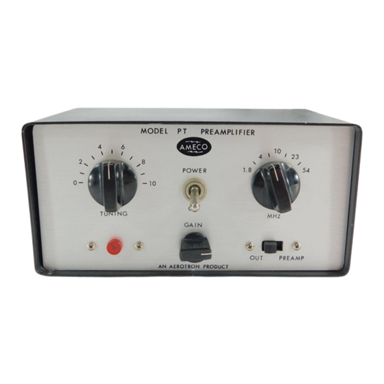
Ameco PT Anleitung Handbuch - Seite 5
Blättern Sie online oder laden Sie pdf Anleitung Handbuch für Verstärken Ameco PT herunter. Ameco PT 9 Seiten. Preamp tube type

OPE
RATION
With
the
P0WER
switch
in
the on (up) position
and
sition,
the transceiver
should work
in
the
normal
the
PREAMP
position, the
pre-ampl
ifier
section of
of the
receiving
system
and, therefore, since
it
as fol
lows:
the
PREAMP
swi
tch
i
n the
OUT
po-
fashlon. With the
PREAMP
switch
in
the
PT
then
will
increase the
gain
is in
operation,
it
should be
used
l.
Turn the
MHz
switch
to a
position
that
includes the desired frequency. For
ex-
ample,
the
2O-meter amateur band
is'14 to
14.35
MHz.
This
is
between
the l0
and
23, therefore the
switch
must be
at the line
between
l0
and
23.
2.
When
a signal is
received,
peak
it
by
"alrrting
the
TUNING
control for
maximum
swing
on
the
receiver
S
meter
or
maximum
volume
if
no
meter
is
used.
ln
tuning
over
a
band,
the tuning
knob
of
the
PT
should be adjusted
fairly frequently.
For
example,
at
AMHz,
it
may
have
to
be
adjusted every 50 kHz.
At
50
MHz,
it
may
have
to
be
adjusted every
200
kHz.
l.
When
the
PREAMP
switch
is left in
the
OUT
position,
the
unit is in
standby
con-
dition with
power
applied
and
its
frame
grid
tube
warmed
up.
lnstantaneous
pre-amplification
is
available
when
the switch
is
placed
in
the
PREAMP
position.
4.
Because
the
PT
adds considerable
amplification
(approximately 20
db)
to
the
re-
ceiver section
of
the transceiver,
which
may
often
have
sufficient gain, partic-
ularly
on
the
lower frequency bands, overloading
resulting in
cross modulation
or
desensitization,
or
both,
may
occur.
For
this
reason,
a
manual
GAIN
control is
in-
cluded on
the
front
panel. Normally,
this control
should be turned
fully
clock-
wise;
however, under
strong
Iocal signal conditions; it
may
often
be found
de-
sirable to
reduce
this control to
a point
where
the local signals
tune considera-
bly
sharper
and, therefore,
occupy
less
space
on the band. Although
this will
re-
duce
the
sensitivity, it will
be very
often
found,
particularly
when
desired
signals are strong,
that
reduction
will
provide an
over-all
and more usable
sig-
nal
than
when
the pre-amplifier
was
not in
the
circuit.
This
is particularly
true
in
those transceivers having considerable front-end gain without provisions
for
separate
RF
gain
and
lF gain controls.
When
switching
the
tuning control
,
or
under certa
i
n
cond
i
ticularly with
the
PT
in
and
out
of
the
circuit
both,
at
i
ncorrect
sett
i
ngs
,
t
ions,
an appreciable
s
i
gnal
GA I
N
control
at
max
imum.
Th
i
s
with
the
band
switch
or
the
i
t
wi I
I
be
not
iced that,
will still
come
through, par-
is
normal
.
Some'transceivers, having
especially
good
AVC
action, will
tend
to
make
tuning
the
PT
difficult, particularly
on strong
signals. This
can be
overcome
by watching
the
S
meter
very
carefully while
peaking
the
PT, peaking up on a
weak
signal, or
peaking
up
on
the
background
noise
in
the
absence
of
a signal.
The
true
worth
of
the
PT
will
be more
fully
realized
under
extremely poor
band
conditions
whenever
signals
are
very
weak.
NOTE.
lf the
receiver
sensitivity
appears
to
be
very Iow,
regardless of
the setting
of
the
band
switch and
the tuning
control,
the fuse/resistor
in
the
antenna
circuitry
should be checked.
(ffre
fuse/resistor in
the
antenna
circuitry is
located on
the
underside
of
the chassis,
at
the
right front.)
