Barnes 3SE-DS Series Installations- und Betriebshandbuch - Seite 7
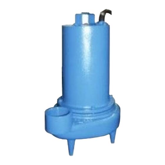
Blättern Sie online oder laden Sie pdf Installations- und Betriebshandbuch für Industrielle Ausrüstung Barnes 3SE-DS Series herunter. Barnes 3SE-DS Series 17 Seiten. Submersible sewage ejector
Auch für Barnes 3SE-DS Series: Installations- und Betriebshandbuch (20 seiten), Installations- und Betriebshandbuch (18 seiten)
MODEL NO HP VOLT/PH
3SE1524DS
1.5
240/1
3SE1594DS
1.5
200-240/3
3SE1544DS
1.5
480/3
3SE1554DS
1.5
600/3
3SE2024DS
2.0
240/1
3SE2094DS
2.0
200-240/3
3SE2044DS
2.0
480/3
3SE2054DS
2.0
600/3
Winding Resistance ± 5%, measured from terminal block. Pump rated for operation at ± 10% voltage at motor
Moisture & Temperature sensor cord for all models is 18/5 SOW, 0.470 (11.9mm) O.D.
OPTIONAL - Temperature sensor cord for 3 phase models is 14/2 SOW, 0.530 (13.5mm) O.D.
SECTION E: PREVENTATIVE MAINTENANCE
As the motor is oil filled, no lubrication or other maintenance
is required, and generally Barnes Pumps will give very
reliable service and can be expected to operate for years on
normal sewage pumping without failing. However as with any
mechanical piece of equipment a preventive maintenance
program is recommended and suggested to include the
following checks:
1) Inspect motor and seal chamber for oil level and
contamination and repair as required per section F-1.
2) Inspect impeller and body for excessive build-up or
clogging and repair as required per section F-2.
3) Inspect motor and bearings and replace as required per
section F-3.
4) Inspect seal for wear or leakage and repair as required
per section F-4.
SECTION F: SERVICE AND REPAIR
NOTE: All item numbers in ( ) refer to Figures 8 & 9.
F-1) Lubrication:
Anytime the pump is removed from operation, the cooling oil in
the motor housing (5) should be checked visually for oil level
and contamination.
F-1.1) Checking Oil:
Motor Housing- To check oil, set unit upright. Remove gland
nut (30a) see Fig. 5, from hex nut (16). Unscrew hex nut (16)
from motor housing (5). DO NOT disconnect wiring from motor
leads. With a flashlight, visually inspect the oil in the motor
housing (5) to make sure it is clean and clear, light amber
in color and free from suspended particles. Milky white oil
indicates the presence of water. Oil level should be to bottom
of plug (19) Fig. 9, when pump is in vertical position.
F-1.2) Testing Oil:
1.
Place pump on it's side, remove pipe plug (19), from
motor housing (5) and drain oil into a clean, dry container.
2.
Check oil for contamination using an oil tester with a
range to 30 Kilovolts breakdown.
3.
If oil is found to be clean and uncontaminated (measure
above 15 KV. breakdown), refill the motor housing as
per section F-1.3.
Hz
RPM
NEMA
FULL
(Nom)
START
LOAD
CODE
AMPS
60
1750
C
16.0
60
1750
D/G
13.3/11.6 35.8/41.2
60
1750
G
5.8
60
1750
G
4.6
60
1750
A
19.0
60
1750
B/D
15.2/13.2 35.8/41.2
60
1750
D
6.6
60
1750
D
5.2
LOCKED
CORD
CORD
ROTOR
SIZE
TYPE
AMPS
inch (mm)
44.6
10/3
SOW
0.690 (17.5)
10/4
SOW
0.750 (19.1)
20.6
10/4
SOW
0.750 (19.1)
16.4
10/4
SOW
0.750 (19.1)
44.6
10/3
SOW
0.690 (17.5)
10/4
SOW
0.750 (19.1)
20.6
10/4
SOW
0.750 (19.1)
16.4
10/4
SOW
0.750 (19.1)
4.
If oil is found to be dirty or contaminated (or measures
below 15 KV. breakdown), the the pump must be
carefully inspected for leaks at the shaft seals (31),
cable assemblies (30) and (32), and hex nut (16),
O-rings (8) and pipe plugs (19), before refilling with oil.
To locate the leak, perform a pressure test as per
section F-1.4. After leak is repaired, refill with new oil as
per section F-1.3.
Important ! - DO NOT overfill oil. Overfilling
of motor housing with oil can create
excessive and dangerous hydraulic
pressure which can destroy the pump
and create a hazard. Overfilling oil voids
warranty.
F-1.3) Replacing Oil:
Motor Housing - Drain all oil from motor housing and dispose
of properly. Set unit upright and refill with (see parts list for
amount) new cooling oil as per Table 1. Fill to pipe plug (19),
on motor housing (5), level as an air space must remain in the
top of the motor housing to compensate for oil expansion (see
Fig. 9). Apply pipe thread compound to threads of hex nut (16)
and pipe plug (19) then assemble to motor housing (5). Insert
friction ring (30b), grommet (30c), another friction ring (30b),
and gland nut (30a) into hex nut (16) and torque to 15 ft. lbs.
Seal Chamber - Set unit on its side with fill plug (19)
downward, remove plug (19) and drain all oil from seal
chamber. Set unit on its side, with plug (19) upward, and refill
completely with (see parts list for amount) new oil as per Table
1. Apply pipe thread compound to threads of pipe plug (19)
and assemble to spacer (50).
TABLE 1 - COOLING OIL - Dielectric
SUPPLIER
BP
Conoco
Mobile
G & G Oil
Imperial Oil
Shell Canada
Texaco
Woco
7
CORD
WINDING RESISTANCE
O.D
EMERSON
MAIN-START
MAIN-START
1.21-2.80
2.21
8.84
13.79
1.21-2.80
2.21
8.84
13.79
GRADE
Enerpar SE100
Pale Paraffin 22
D.T.E. Oil Light
Circulating 22
Voltesso-35
Transformer-10
Diala-Oil-AX
Premium 100
G.E.
---
2.23
8.92
13.95
---
2.23
8.92
13.95