American Standard TOWNSQUARE 2555.900 Einbauanleitung
Blättern Sie online oder laden Sie pdf Einbauanleitung für Sanitärprodukt American Standard TOWNSQUARE 2555.900 herunter. American Standard TOWNSQUARE 2555.900 3 Seiten. Deck-mount bath filler with everclean finish
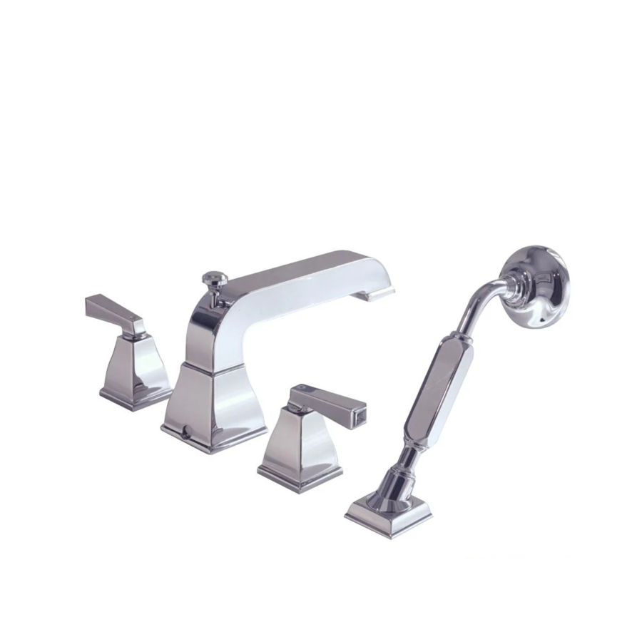
TOWNSQUARE
DECK-MOUNT BATH FILLER
with
EverClean™ Finish
Congratulations on purchasing your American
Standard faucet with EverClean finish found
only on American Standard faucets.
EverClean Finish
• One wipe effortlessly removes spots
• Eliminates the need for cleaners and scrubbing
• Permanent surface protectant remains beautiful
for the life of the faucet
• EverClean™ available on: Polished Chrome, Satin Nickel,
Stainless Steel, Polished Brass (or any combination of these finishes)
To ensure that your installation proceeds smoothly-please read these instructions carefully before you begin.
IMPORTANT NOTICE TO INSTALLER!
Please check with local Code Authority for the installation requirements of this product. Some codes require an
additional temperature mixing valve to limit the maximum hot water temperature and vacuum breaker
(for products with hand spray) to be installed with this product.
Required Tools
Phillips Screwdriver
Flat Blade Screwdriver
Channel Locks
1
SPOUT ASSEMBLY
CAUTION
Turn off hot and cold water supplies before beginning.
Insert SPOUT SHANK (1) through center hole of MOUNTING LEDGE.
Make sure that the RUBBER RING (2) is properly seated in RECESS
at base of SPOUT (3).
Assemble RUBBER WASHER (4) and BRASS WASHER (5) onto
SHANK (1). From underside of ledge secure SPOUT (3) into position
with LOCKNUT (6).
RECESS
4
6
ROUGHING-IN
DIMENSIONS
Adjustable Wrench
Wrench
(Supplied)
3
1
2
MOUNTING
LEDGE.
5
Installation
Instructions
2555.900
2555.901
8-1/4
3-5/8
1-1/8 D.
4
3/4-14 MALE
N.P .T. INLETS
2
PREPARE TUBE AND TEE ASSEMBLY
Prepare TUBE and TEE ASSEMBLY (1) to fit center to center
VALVE (2) location (between 6-1/2" and12"). If necessary,
cut and/or bend TUBING carefully. Make sure tube bend is
close to the TEE (1) so that it will not effect the compression
joint at the VALVE CONNECTION.
Remove COUPLING NUT (3) and FERRULE (4) from each
VALVE (2) and slide onto TUBING (5).
4
3
NOTE
VALVE inlet is 3/4-inch NPT male connector.
Certified to comply with ANSI A112.18.1M
ADJ. 6-1/2 TO 12
1-1/4
MAX.
3
(C)
(H)
12 MAX
1-1/16 D.
ADJ. 6-1/2 TO 12
1
5
3
4
MOUNTING
SURFACE
1-1/2 MAX.
1-3/16 D.
2