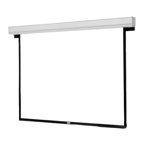
When using your video equipment, basic safety precautions should always be followed, including the
following:
1. R ead and understand all instructions before using.
2. P osition the cord so that it will not be tripped over, pulled, or contact hot surfaces.
3. If an extension cord is necessary, a cord with a current rating at least equal to that of the appliance
should be used. Cords rated for less amperage than the appliance may overheat.
4. To reduce the risk of electric shock, do not disassemble this appliance. Contact an authorized
service dealer when repair work is required. Incorrect reassembly can cause electric shock when
the appliance is used subsequently.
5. The use of an accessory attachment not recommended by the manufacturer may cause a risk of
fire, electric shock, or injury to persons.
PRE-INSTALLATION
1. Carefully unpack screen and remove outer wrapping from case.
2. Make sure to recheck measurements of screen location before installation.
CASE INSTALLATION
1. The case provides multiple attachment points for bolts, cables, or threaded rod. Page 7 shows threaded rod
installed. The variable position-mounting bracket may be located anywhere along the length of the case. It is
recommended to keep the brackets spaced evenly enough to distribute the weight of the screen.
The case has a self-trimming flange around the bottom. Ceiling tiles or drywall may be placed on top of this flange
to provide a finished appearance.
2. After securing the case in the ceiling check that the case is level and plumb.
3. Install electrical connections that apply to your unit. Refer to the following diagrams for proper installation. The
diagrams on page 4 are for standard controls; the diagrams on page 5 are for SCB100 controls and page 6 for
SCB200 controls. The terminal block for the wall switch connections is located under the metal housing
surrounding the junction box. Remove two screws for access.
IMPORTANT SAFETY INSTRUCTIONS
SAVE THESE INSTRUCTIONS
SCREW FOR
SECURING ROLLER
ACCESS DOOR
FABRIC DOOR
1
ACCESS
DOOR
FIGURE 1

