AMERITRON ARI-500 Gebrauchsanweisung - Seite 3
Blättern Sie online oder laden Sie pdf Gebrauchsanweisung für Schalter AMERITRON ARI-500 herunter. AMERITRON ARI-500 13 Seiten. Automatic band switch for the ameritron als-500m; ameritron als-600 amplifiers
Auch für AMERITRON ARI-500: Gebrauchsanweisung (16 seiten)

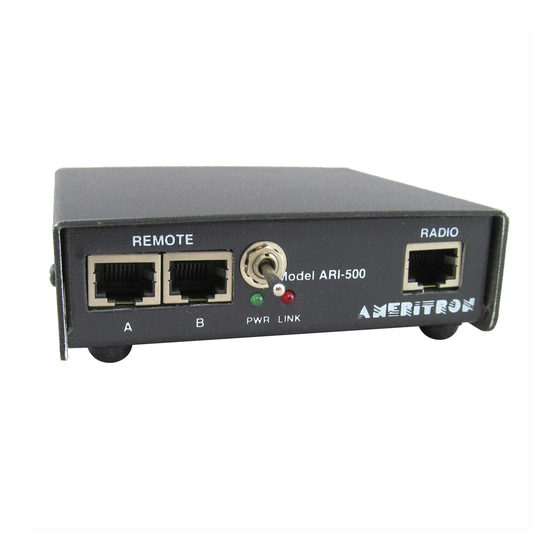
ARI-500 Automatic Band Switch for ALS-500/600
Installation
The ARI-500 connects to the REMOTE A/B jacks on the front of the amplifier. Two RJ-45 cables are supplied to connect jack A
and B from the ARI-500 to the REMOTE A/B jacks on the ALS-500M or ALS-600.
1.
Place the ARI in a suitable location.
2.
Ensure the amplifier power switch is OFF and the amplifier's frequency select switch is in the REMOTE position.
3.
Plug one of the patch cords into AMP A on the ARI-500. Route the other end to the amplifier and connect it to the REMOTE
A amplifier input.
4.
Plug the other patch cord into AMP B on the ARI-500. Route the other end to the amplifier and connect it to the REMOTE B
amplifier input.
Operating ALS-500RC with the optional ARI-500
Skip this section and go to ARI-500 Transceiver Compatibility if the ALS-500RC is not used.
The optional ALS-500RC Remote Control Head can be used with the ARI-500. The ALS-500RC provides current metering (ALS-
500M) or RF power output metering (ALS-600), TX and O/L (Fault) indications of the amplifier, and O/L resetting of the amplifier
via the ALS-500RC ON/OFF switch by cycling power on the ALS-500M, or operating as a OPERATE/STANDBY switch with the
ALS-600.
To use the ALS-500RC Remote Control Head with the ARI-500:
1) Connect a RJ-45 patch cable to Remote port A of the ARI-500.
2) Connect the other end of this RJ-45 cable to port A of the ALS-500RC remote.
3) ALS-500RC Port B is not used in this application.
Note:
JMP 2 inside the ARI-500 must be set as described below when the ALS-500RC is used:
1) JMP 2 in the 1-2 position (Fig. A): Factory default. Must be strapped this way when the ALS-500RC is NOT used.
2) JMP 2 in the 2-3 position (Fig. B): Strapping position when using the ALS-500RC. The Current/RF Power Meter, Power,
TX and O/L indicators are all functional. The ARI-500 Auto O/L Reset (Fig. C) is automatically disabled. The ALS-500RC
POWER switch turns the ALS-500M power ON and OFF, and functions as the ALS-600 OPERATE/STANDBY switch.
Manually reset O/L on both amplifiers by switching the ALS-500RC's POWER Switch OFF and then ON. When the ALS-
500RC POWER is switched ON, it takes about four seconds for the ALS-500 to turn on or the ALS-600 to reset.
JMP 2
FIGURE A
(Factory Default)
Note: JMP 2 MUST be in the Factory Default position (FIGURE A) if the ALS-500RC Remote Control Head is NOT used.
Note: JMP 3 should be set to OFF (Figure C) when using the ALS-500RC, as the ALS-500RC provides manual reset functionality.
ARI-500 Transceiver Compatibility
The ARI-500 is compatible with most ICOM, Kenwood and Yaesu radios for reading band data information and detecting transmitter
keying. Additionally, the ARI-500 low drive current keying interface is compatible with virtually any transceiver's amplifier keying
output. Newer Kenwood radios have a DB-9 male connector for computer control. Serial data is read from this port to get the band
data. ICOM Transceivers use a "step voltage" for band data. A voltage of 0-8 volts is output from the band data pin of the accessory
jack. Yaesu, older Kenwood, and Elecraft K3 radios output band data in a 4-line BCD format (the Unified Microsystems plan).
Many other transceivers use the 4-line BCD standard as well. Check your transceiver's instruction manual to see if this is the case. If
so, it will also be compatible with the ARI-500.
Instruction Manual
JMP 2
FIGURE B
3
