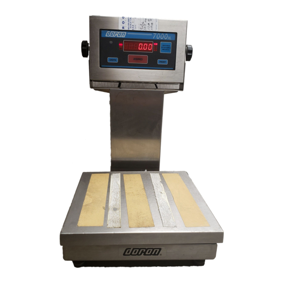
Doran 7000XL Gebrauchsanweisung - Seite 3
Blättern Sie online oder laden Sie pdf Gebrauchsanweisung für Messgeräte Doran 7000XL herunter. Doran 7000XL 5 Seiten. Digital weight indicator
Auch für Doran 7000XL: Benutzerhandbuch (7 seiten), Benutzerhandbuch (5 seiten)

Latching Print Request Setup Menu........................................................................ 19
Printer Data Output Setup Menu ............................................................................. 20
Output Formats ....................................................................................................... 20
Baud Rate Setup Menu ........................................................................................... 20
Serial Data Handshaking Setup Menu .................................................................... 21
Units Conversion Setup Menu................................................................................. 21
Start Up Units Selection Menu ................................................................................ 21
Push-button Function Setup Menu .......................................................................... 22
Remote Push-button Configuration Menu ............................................................... 22
Legal For Trade Setup Menu .................................................................................. 22
Scale Resolution Setup Menu ................................................................................. 22
Unit On Timer (8000XL only)................................................................................... 23
Default all Scale Parameter settings ....................................................................... 23
Raw Counts Display Mode ...................................................................................... 23
Calibration and Parameter Menu Exit...................................................................... 23
Data Communications .............................................................................24
Introduction to data communications:......................................................................... 24
Printer Modes: ............................................................................................................ 25
Transmit on demand (tod): ........................................................................................ 25
Continuous print (CP): ................................................................................................ 25
Auto Print 1 (AP1 ) : ....................................................................................................... 25
Auto Print 2 (AP2): ...................................................................................................... 25
Data output format:..................................................................................................... 26
"F0" Format: .............................................................................................................. 26
"2d" Format: .............................................................................................................. 26
"SSP" format:............................................................................................................... 26
"Fg" Format:............................................................................................................... 26
Table 2: Doran serial protocol ................................................................................. 27
Specifications and Interconnect Data ....................................................28
Specifications: ............................................................................................................ 28
Table 3: Scale Specifications .................................................................................. 28
Interconnect Data: ...................................................................................................... 28
Table 4: TB1 Load Cell Connections....................................................................... 28
Table 5: P2 Options Connections............................................................................ 29
Table 6: J1 Power Connections............................................................................... 29
P3 Keyboard Connections....................................................................................... 29
Table 7: P3 Keyboard Connections......................................................................... 29
Fig. 6: Connector J2, Remote switch cable assembly ............................................. 29
Fig. 7: Connector J2, Serial cable assembly ........................................................... 30
Table 8: Serial Output pin description ..................................................................... 30
Fig. 8: RS232 Output DB9 Connector (optional) ..................................................... 30
Fig. 9: Installation of EMI / RFI / ESD protection devices. ....................................... 31
Fig. 10: Jumpers and Connector Locations............................................................. 32
Table 9: Board Jumper settings............................................................................... 32
4-20mA Analog Output (optional)...........................................................33
Introduction ................................................................................................................ 33
Setup.......................................................................................................................... 33
Operation ................................................................................................................... 33
Fig. 11: 4-20mA analog option board ...................................................................... 33
2
