ASTRO-PHYSICS 900 German Equatorial Handbuch - Seite 6
Blättern Sie online oder laden Sie pdf Handbuch für Zubehör ASTRO-PHYSICS 900 German Equatorial herunter. ASTRO-PHYSICS 900 German Equatorial 12 Seiten. Polar alignment telescope and illuminator (pasill)
Auch für ASTRO-PHYSICS 900 German Equatorial: Schnellstart-Handbuch (2 seiten), Handbuch (3 seiten)

each side of the mount, to make fine adjustments in azimuth. You must back off the opposing azimuth knob in
order to move the other knob in that direction. Please refer to the following diagram.
4. Altitude (latitude) adjustments: Loosen the altitude locking knobs. Move the polar axis up or down with the large
altitude adjustment knob located in the front of the polar axis assembly. The Tommy bar can be positioned in any of
the threaded holes located in the altitude adjustment knob. Use this bar to help you turn the knob. Please refer to
the diagrams on page 3. We have found that fine altitude adjustments can also be made by using the turnbuckle on
the north leg of our pier.
5. Continue your azimuth and altitude adjustments until you can sight Polaris in the polar alignment sight hole. At this
point, you have achieved rough polar alignment, which may be sufficient for most casual visual observations. When
the R.A. motor is engaged, it will compensate for the rotation of the earth and keep the target object within the
eyepiece field of view. Your target object will slowly drift since polar alignment at this stage is only approximate.
However, you can make corrections with your hand controller, as we will discuss later.
6. Tighten the altitude locking knobs by hand.
7. Tighten the pier knobs firmly by hand.
ASSEMBLE DECLINATION AND RIGHT ASCENSION AXES
Do not have your telescope or counterweights connected to the Dec.
axis assembly for either assembly or disassembly of the Dec. and
R.A. axes.
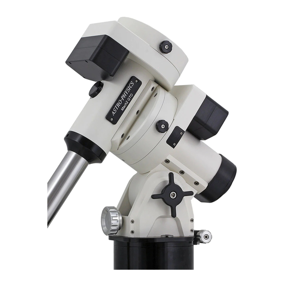
1. Position the R.A. axis as shown in the upper diagram on the
right, with the "guide" notch "A" at the top, opposite the altitude
adjuster knob. Firmly tighten R.A. clutch knobs.
2. During shipment, the Dec. axis assembly lock knobs will be
fully screwed into the Dec. axis assembly. For correct
assembly, these lock knobs should be unscrewed at least 7 full
turns and no more that 8.5 full turns. This is between 5/16" and
3/8" out from the "shipped" tightened position.
IMPORTANT: These lock knobs can be completely removed
from the Dec. axis assembly with about 9.5 full turns out.
3. Position the Dec. axis above R.A. axis as shown in the lower
diagram, a light movement (wiggle) in the downward direction
(arrow "A") will help to correctly seat the principle dovetail(s)
and parallel guides.
4. When both Dec. and R.A. assemblies are fully seated,
hand tighten both Dec. lock knobs.
5. Thread the counterweight shaft into the Dec. axis.
6. Attach the cradle plate with the appropriate screws.
7. Remove the hand knob and safety washer from the base of
the counterweight shaft. Add sufficient counterweights (10
or 18 lb. counterweights are available) to the declination
shaft to balance the telescope you intend to use. Always
use two hands to attach or move them on the shaft.
8. Reattach the hand knob and safety washer to the end of
the declination shaft. This will help to prevent injury if
someone accidentally loosens the counterweight knob.
NOTE:
Firm tightening of the counterweight knob will
not damage the surface of the counterweight shaft. The
pin that tightens against the stainless counterweight shaft
is constructed of brass. Likewise, a bronze sleeve that
has been press-fit into the center of the counterweight will
prevent marring of the shaft as you move the
counterweight up and down.
- 6 -
