bolid IP 212-31 DIP-31 Betriebshandbuch - Seite 2
Blättern Sie online oder laden Sie pdf Betriebshandbuch für Sicherheitssensoren bolid IP 212-31 DIP-31 herunter. bolid IP 212-31 DIP-31 4 Seiten. Threshold photoelectric smoke detector
4
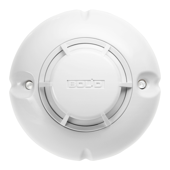
DESIGN
The essential parts of the DIP-31 detector are as follows (see Figure 1): the detector base (Position 1) with guiding grooves (Position 2), two light
emitting indicators (Position 3), the printed circuit board and the sensing chamber (Position 4), the detector body (Position 5), the detector cover
(Position 6), the sensing chamber cover (Position 7), and the screen (Position 8).
5
MOUNTING AND DETACHMENT
5.1 The detector is to be mounted to the surface of bearing structures using its base (see Figure 2). To install the detector base, drill two holes into the
surface according to the drilling pattern in Figure 2 and attach the base by means of screws and wall plugs or tapping screws.
5.2 To install the detector onto fire resistant tiles of suspended ceiling, use MK-2 or MK-3 mounting kit for attaching the detector base (Figure 3,
Position 1). Make a mounting hole for the mounting kit according to the marking (Figure 3).
5.3 Until installation works are completed, the sensing chamber of the detector should be covered by the protection cover provided (Figure 3, Position 3).
5.4 To protect the detector against unauthorized removing or to provide secure attachment in the presence of vibrations
following.
Prior to installing the detector base, detach the key (Figure 4, Position 3) from it and cut out the rib (Figure 4, Position 1) of the locking click
(Figure 4, Position 2).
2
Figure 1
Figure 2
1 -
Base
2 -
Guiding grooves
3 -
LED Indicators
4 -
Sensing Chamber with PCB
5 -
Detector Body
6 -
Detector Cover
Sensing Chamber Cover
7 -
8 -
Screen
B
Figure 3
Figure 4
,
lock the detector by doing the