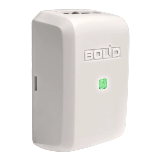
bolid S2000-AR2 Installationshandbuch - Seite 3
Blättern Sie online oder laden Sie pdf Installationshandbuch für Kontrolleinheit bolid S2000-AR2 herunter. bolid S2000-AR2 4 Seiten. Addressable double-input module

4 WIRING
4.1 Polling Loop Wiring
4.1.1 Connect the polling loop wires to the contacts "+" and "−" of the module terminal block
marked as "ДПЛС" on the PCB, observing polarity. Not observing polarity will result in non-
operability of the polling loop.
4.1.2 For the polling loop it is advised to use twin twisted-pair wires.
4.2 Detector Wiring
4.2.1 Connect alarm dry contact outputs of non-addressable detectors to terminals MC1 and
MC2 (marked as "КЦ1" and "КЦ2" respectively) in line with the schematic in Figure 4.
4.2.2 The resistance of the monitored circuit wires shall not exceed 100 Ohm while the leakage
resistance shall be at least 50 kOhm.
4.2.3 If a monitored circuit is not in use connect a 10 kOhm termination resistor to its contacts.
4.3 Close the module enclosure as shown in Figure 3.
S2000-KDL
PL-
PL+
AD
R1
D1
R
EOL
Variant A
AD: Addressable Device
MC: Monitored Circuit
D1: A normally closed fire detector
D2: A normally open fire detector
D3: A normally open intrusion detector
D4: A normally closed intrusion detector
R1: An additional resistor MF1/4 - 20К ±5%
R2: An additional resistor MF1/4 - 4К7 ±5%
R
: A termination resistor MF1/4 – 10К ±5%
EOL
Figure 4. Schematic for External Wiring of S2000-AR2 Rev.02
http://bolid.ru
ДПЛС
MC+
R
EOL
MC-
Variant B
R2
MC+
D2
MC-
To detectors
(connection variant
MC2
A, B, or C)
To detectors
MC1
(connection variant
A, B, or C)
D4
MC+
R
D3
EOL
MC-
Variant C
3
