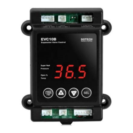
DOTECH EVC10B-R4 Benutzerhandbuch - Seite 3
Blättern Sie online oder laden Sie pdf Benutzerhandbuch für Controller DOTECH EVC10B-R4 herunter. DOTECH EVC10B-R4 8 Seiten. Electronic expansion valve controller

: Details of terminal
No.
Definition
Description
J1.1
+24V
J1.2
AC / DC
J1.3
24V
-24V
J1.4
J2.1
SIG
RUN
J2.2
GND
J3.1
TRX+
RS485
J3.2
TRX-
J4.1
N.O
J4.2
AUX-RLY
COM
J4.2
N.C
1) Operation start and stop instruction
If SIG signal is short circuited (on), it will start to run. In case of opening (off),
operation will be stopped and expansion valve is closed immediately.
3) Selection of electronic expansion valve
First of all, EVC10B needs to setup EEV mode to fit features of electronic
expansion valve. If EEV mode does not meet operation features of electronic
expansion valve, there can be malfunction. Please check it without fail. Operate
only number 2 and 3 of DIP SWITCH (DSW). After changing of setting, push
RES button on the right of product and restart. Users may input power
again.
DIP
DIP
MAKER & MODE
SW 2
SW 3
SANHUA-DPF(Q), DPF(R)
JAHWA-SEV, JHEV
OFF
OFF
FUJIKOKI-CAM
SAGINOMIYA-
UKV,SKV,VKV,PKV,AKV
SANHUA-DPF(O)
OFF
ON
FUJIKOKI-EDM
GREEN-GV321,521,641
ON
ON
Direct input by user
※ In case of DPF(O)-8.0, change set value after altering into user mode.
(DIP SW 2,3 = ON)
Function
Expansion valve
excitation type
Expansion valve TOTAL
PULSE
Expansion valve OPEN
PULSE
Expansion valve DRIVE
SPEED (PPS)
Power input AC24V or DC24V+
Power input AC24V or DC24V-
Run / Stop signal input
Signal common
RS485 comm. TRX+(A)
RS485 comm. TRX-(B)
Auxiliary relay - Normal Open contact
Auxiliary relay - common
Auxiliary relay - Normal Close contact
SPEC.
1-2 PH excitation type
500 PULSE
30 PPS
2 PH excitation type
2000 PULSE
100 PPS
Setup at
parameter 3 group
CODE
Min.
Max.
Default
0
1
2
EVD
100
999
200
EVP
0
999
100
EVO
1
18
1
EVS
No.
Definition
J5.1
J5.2
P-SENS
J5.3
J6.1
T-SENS
J6.2
J7.1
J7.2
J7.3
EEV
MOTOR
J7.4
J7.5
J7.6
2) Utilization of auxiliary rely
Auxiliary relay can be used for alarm or compressor ON/OFF or liquid valve
ON/OFF In case of Pd= Off, use it as an alarm purpose.
If users enter pump down time (1~180 sec), it will be used for ON/OFF signal of
compressor.
4) Selection of control mode
Operation
mode
1
Automatic
OFF
mode
Drive
ON
Manual
ON
operation
Temp.
OFF
control
※ It does not detect alarm at drive and manual operation mode.
Changed
Value
2
250
100
5
-3-
Description
+5V
Power output for pressure sensor(+5V)
S1
Pressure sensor signal input
GND
Pressure sensor power signal common
S2
Temperature sensor
GND
Temperature sensor common
A
EEV phase 1(A)
B
EEV phase 1(B)
A#
EEV phase 2(A#)
B#
EEV phase 2(B#)
COM
EEV common
COM
EEV common
DIP SW
Description
4
- Superheat control
OFF
- Possible to operate valve via
RS485 comm.
- Operate valve receiving external
ON
signal from J5 port
- Operate valve using UP/DOWN button.
OFF
- Possible to operate valve via
RS485 comm.
- Precise temp. control by controlling hot gas
ON
bypass
EVC10B R20140821
