Baumer DENEX Gripper LED Benutzerhandbuch - Seite 7
Blättern Sie online oder laden Sie pdf Benutzerhandbuch für Zubehör Baumer DENEX Gripper LED herunter. Baumer DENEX Gripper LED 24 Seiten.

5
ELECTRICAL INSTALLATION
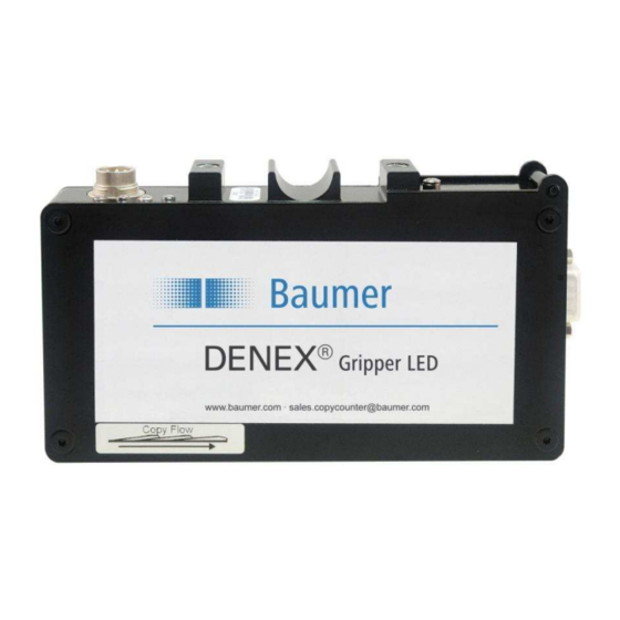
The copy sensor has a 7-pin male connector with the following pin-out:
Matching female connector is Amphenol Tuchel T3476 001, delivered with the sensor.
Pin 1 :
+24Vin
Pin 2 :
+ Output (Collector)
Pin 3 :
+ Speed Sensor Input
Pin 4 :
- Speed Sensor Input
Pin 5 :
- Output (Emitter)
Pin 6 :
0V
Pin 7 :
No function (connected to pin 6 internally)
5.1
Power Connection
Proper wiring techniques are essential for successful system installation. To reduce the
effects of electrical noise interference and static discharge, the procedures outlined in this
section must be strictly followed.
The sensor shall be connected to 19 - 30V DC regulated power.
It must be free from transients!
Never connect or disconnect any cables when the power is on!
The normal current consumption is around 200mA.
5.2
Output Signal
The output is a normally open, opto-isolated transistor. Every output pulse is signaled as a
closing of the output; see "DIP-Switch Settings" in chapter 6.4.
The specification for the output opto-coupler is as follows:
Max load current:
Max voltage:
User Manual DENEX Gripper LED
Version 2013-02, V1.4
150mA
35V DC
7/24
www.baumer.com
Baumer Electric AG
Frauenfeld, Switzerland
