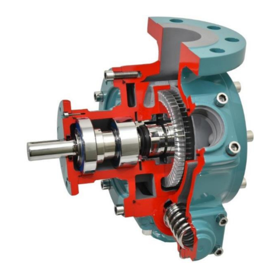
Dover Ebsray R75 Handbuch für Installation, Betrieb und Wartung - Seite 8
Blättern Sie online oder laden Sie pdf Handbuch für Installation, Betrieb und Wartung für Water Pump Dover Ebsray R75 herunter. Dover Ebsray R75 12 Seiten. Regenerative turbine pump

5.6
BEARINGS OR SHAFT REPLACEMENT
A press and two pieces of flat bar are required to remove the
Shaft (21) and Bearing's fixed assembly from the Bearing
Housing and also to remove and replace the Bearings from the
Shaft.
To replace the Drive End Bearing (DEB, 24) and the Inspection
End Bearing (IEB, 23) complete steps one to five in SECTION
5.4, then complete the following steps:
1.
Remove the Driver Key (34).
Remove the Bearing Cap's (99) eight cap head
2.
setscrews (99B). Remove the Bearing Cap, remove
the Bearing Cap's O-ring (99A), discard and replace
with lightly lubricated new O-ring.
3.
Replace the Bearing Dust Seal (33)
4.
Push or gently tap the Impeller end of the Shaft (21)
and Bearing's fixed assembly from the Bearing
Housing.
5.
Remove the Bearing Circlip (25), starting with the
DEB, support the Impeller side of the DEB's inner
raceway and press the driven end of the Shaft until
the DEB is pushed off the Shaft.
6.
Then support the driven side of the IEB and press
from the Impeller end of the Shaft. Press until the IEB
is pushed off the Shaft.
7.
To press the IEB onto the
Shaft fully support the inner
raceway of the IEB using two
pieces of flat bar (See Figure
9). Locate the Impeller end of
the Shaft (Impeller has a
10mm wide keyway) through
the IEB. Press the driven end
of the shaft until it fully rests
on its shoulder.
8.
To press the DEB onto the Shaft, fully support the
inner raceway of the DEB and press the Impeller end
of the Shaft onto the DEB. Press the Impeller end of
the Shaft until the circlip groove is fully exposed.
9.
Fit the Bearing Circlip. Press the driven end of the
Shaft and Bearing's fixed assembly into the Bearing
Housing until the IEB is fully seated in the Bearing
Housing.
10.
Fit the Bearing Cap over the driven end of the Shaft.
Check the Bearing Cap's O-ring is correctly located
before, hand fitting the eight cap head setscrews.
Torque the setscrews to 13 Nm (10 ft-lb's).
11.
Replace the Driver Key. Continue on with step six of
SECTION 5.4.
5.7
VALVE & VALVE SPRING REPLACEMENT
1.
Remove the four Valve Cover cap head setscrews
(103B).
2.
Discard the Valve Cover O-ring (103A), and replace
with a lightly lubricated new O-ring.
3.
Remove the Bypass Spring. Then remove the Valve
(105). If the Valve is stuck use pliers or similar to pull
the Valve out.
Be careful not to scratch the Valve with the pliers as any
foreign materials left inside the pump WILL seriously
4.
5.
5.8
Looking at the pump from the shaft end with the inlet flange
up, the R75 can be configured with the alternate inlet on the
left or the right.
1.
2.
3.
The cover is a very neat fit into the pump body. Do not
use excessive force to remove the cover. If the cover
gets stuck, gently rock loose or gently tap loose with a
4.
5.
6.
7.
Figure 9
8.
This is guaranteed as one of the bolt holes is 1.5 degrees
out of pitch. In other words if all eight bolts do not start in
the Body's tapped holes the angular orientation is not
9.
10.
11.
12.
13.
8
NOTE:
damage the pump.
Fit the new Valve and or Bypass Spring then the
Valve Cover.
Ensuring the valve cover O-ring is located properly,
hand fit the four Valve Cover cap head setscrews.
Torque setscrews to 58 Nm (43 ft-lbs).
RE-HANDING THE PUMP
Remove the eight cover cap head setscrews (6).
If required fit two of the setscrews to the tapped
jacking holes.
Remove the Cover (2), remove the Cover O-ring (4),
discard and replace with lightly lubricated new O-ring.
NOTE:
soft mallet.
Lightly lubricate and refit to Cover, ensure that the O-
ring is properly fitted.
Remove the eight bearing housing cap head
setscrews (27). Repeat step two if required.
Remove the Bearing Housing (20), remove the
Bearing Housing O-ring (26), discard and replace with
lightly lubricated new O-ring.
Lightly lubricate and refit to the Bearing Housing,
ensure that the O-ring is properly fitted.
Refit the Bearing Housing to the opposite side of the
pump. The Bearing Housing inlet port aligns to the
Body (1) inlet port.
NOTE:
correct.
Do not force the Bearing Housing into the Body. If it
gets stuck, gently rock loose or gently tap in with a
soft mallet.
Do a final check to ensure the Bearing Housing O-
ring is correctly located.
Fit all eight bearing housing cap head setscrews and
torque to 100 Nm (75 ft-lbs).
Fit the Cover to Body, note that the raised cast text
"IN" aligns with the Body's inlet flange. Again beware
the close fit and don't force the cover in. Again check
that the Cover O-ring is correctly located.
Fit all eight cover cap head setscrews and torque to
100 Nm (75 ft-lbs).
