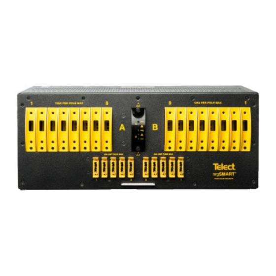
Amphenol Telect nrg600BT08-M Installationshandbuch - Seite 5
Blättern Sie online oder laden Sie pdf Installationshandbuch für Stromkreisunterbrecher Amphenol Telect nrg600BT08-M herunter. Amphenol Telect nrg600BT08-M 20 Seiten. 600a load center with nrgsmart remote monitoring

Specifications
Inputs
Voltage range, nominal voltage
Max. input load rating
Short circuit withstand rating
Nominal power loss at full load
Percentage of full power
dissipation at nominal voltage
Max. input interrupt device
Input terminal studs
(with nuts, flat washers and
spring washers) for dual-hole
compression lugs
Input wire size
Dual-Hole Outputs
Max. output single-pole, long-
delay circuit breaker (ea.)
Max. output TPS or TLS
Max. output load (ea.) -
continuous
Minimum short circuit
interrupt rating
Output terminal studs (with
KEPS, nuts and washers)
for dual-hole compression
lugs
Output wire size
GMT Outputs
Max. GMT output fuse (ea.)
Max. GMT output load (ea.) -
continuous
Minimum short circuit interrupt
rating
GMT output terminals for
compression lugs
GMT output wire size
Dry Contact Alarms
Alarm wire size
Alarm terminals
Relay contact ratings
Max. alarm power rating
nrg600BT08-M
-40V to -60V (Nominal -48 VDC)
600A per side at max.
5000A (breakers/fuses); 450A GMT
Less than 75W per side @ 28,000W
full load per side (600A x 48V)
Less than 1%
750A
•
Two pair of 3/8 – 16 studs on 1
in. centers per terminal [max.
lug width of 1.94 in. (49.2 mm)]
per pair
•
Torque nut (using 9/16 in. or 15 mm
wrench) to 150 in.-lb (~17 N•m),
max.
#1 AWG to 750 MCM
100A
125A
100A
5000A
•
1/4 - 20 studs on 5/8 in. centers
[max. lug width of 0.680 in.
(15.8 mm) for a BATT terminal
and
0.70 in. (17.7 mm) for a RETURN
terminal].
•
Torque bolts (using 7/16 in. or 12
mm wrench) to 50 in.-lb (~5.5
N•m), max.
#14 AWG minimum
20A
14A
450A
•
10 removable, #6-32 panhead
screws (max. lug width of 0.29 in.
[7.4 mm]).
•
Torque to 6.3 in.lb (~0.7N•m), max.
#22 AWG to #12 AWG, depending on
output fuse rating
#22 to #18 AWG
Wire wrap
Dry Form-C contacts (1A @ 30 VDC,
0.5A @ 60 VDC, 0.3A @ 125 VAC)
@24V: 72 mA (1.73W)
@48V: 147 mA (7.06W)
Grounding
Earth GND terminal bolts
(with washers) for dual-hole
compression lug
Ground wire size
Voltage Sensor
Sensor accuracy
Voltage measurement range
Feed voltage detection
NOTE:
•
Voltage measurement may be slightly different than at input
terminal blocks due to the voltage drop within the panel.
•
Sensors are factory calibrated and do not require user adjustment.
Communication
nrgNET sensor and alarm
card power
(via nrgNET cabling
connection to an
nrgCONTROL-BT controller)
nrgNET data communication
nrgNET connector
nrgNET connector functions
LED Alarm Indicators
(requires nrgNET & controller
for power)
Supported protocols
Fit and Finish
Material
Color
Mechanical
Dimensions (L x W x H):
Rack space
Environmental
Operating temperature
Humidity
Weight (approximate)
Installed
Shipping
Compliance
Warranty
Standard 1-year warranty on all parts.
•
•
The warranty is extended through the addition of the annual
maintenance and support contract (nrgSMART-APSC)
5
All rights reserved. 12.05.19 145121-2 A0
•
Two pair of 1/4 - 20 threaded
holes on 5/8 in. centers.
•
Torque bolts (using 7/16 in. or 12
mm wrench) to 50 in.-lb (5.5 N•m),
max.
#2 AWG recommended
0 to -19.99V: ±0.3V
-20V to -60V: ±0.1V
0 to -60 VDC
0 to -19.99V: Alarm
-20V to -60V: Normal
-48 VDC nominal
*NOTE: The nrg600BT08-M chassis
MUST BE connected to an
nrgCONTROL-BT controller via
nrgNET cabling for LED Alarm
Indicators to function
RS-485
Removable 5-pin connector with
screw down terminals
nrgNET IN from the nrgCONTROL or
nrgSMART Panel, nrgNET OUT to next
inline nrgSMART panel
A/B bus power
A/B fuse alarms
nrgNET Comms active
Proprietary nrgNET used to
communi- cate between panels and
controller
14-gauge steel
Pewter grey powder coat
12" x 17.25" x 7"
4RU
-5° to +44°C
0 to 90%, non-condensing
47 lb (21.3kg)
49.1lb (22.3kg)
UL, NEBS level 3
Amphenol Network Solutions
509.926.6000 – amphenol-ns.com
