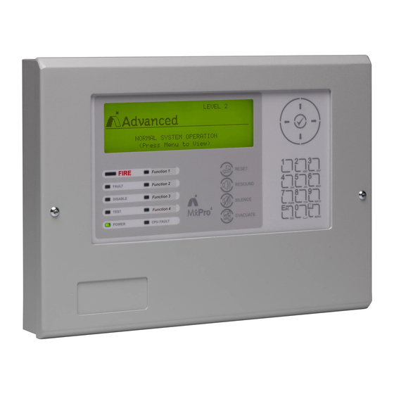
Advanced MxPro4 Series Handbuch - Seite 5
Blättern Sie online oder laden Sie pdf Handbuch für Feueralarm Advanced MxPro4 Series herunter. Advanced MxPro4 Series 12 Seiten. Sounder booster
Auch für Advanced MxPro4 Series: Installationsblatt und Schnellreferenzhandbuch (4 seiten), Handbuch (6 seiten)

1.2 Mounting the Enclosure
First, remove the enclosure cover, which is held
in place by tamper resistant hexagon key screws.
These require the use of a 2.5mm Allen Key.
Remove the two screws securing the chassis on
which the display and all the electronics are
mounted. Put the chassis to one side, observing
normal anti-static precautions.
Remove the required knockouts for the incoming
supply/earth and the network data cables.
Fix the unit to the wall using the mounting holes
in each corner of the back box.
1.3 Electrical Connections
Fit the cable glands for the incoming supply and
network data cables. Cable Anchor Points are provided
in the rear of the back box to enable these cables to be
securely fastened using tie-wraps.
Connect the incoming power supply earth wire to the
earth stud in the back box.
Re-fit the chassis plate. Connect the 24V DC supply
feed to the SUPPLY +24V and 0V terminals.
Note the power supplied used MUST BE designated a
Safety Extra Low Voltage (SELV) supply.
A stand-alone power supply with clean-contact fault
output contacts can be monitored by taking them to the
"FLT-INPUT" connections on the left hand terminal
block. A 10K series resistor should be connected to the
relay terminals. If fault monitoring is not required a
10K resistor should be left in the "FLT-INPUT" terminal
block.
Connect the 2 core twisted pair network data cable to
the A and B terminals.
Connect the data cable screen to the network SCN
terminals. Note that special screen termination circuits
are included on the circuit card to prevent mains
frequency earth-loop currents flowing between network
nodes. The data cable screen MUST NOT be
connected to any other earth point.
226mm
35mm
Back Box Fixing
Points x4
Recommended
Power
Power
Knockout Usage
IN
OUT
Please refer to document 680-027 for more detailed
information on the Ad-Net network.
All electrical wiring installation work should be carried
out in accordance with the code of practice
applicable in the country of installation.
To maintain electrical integrity of the SELV wiring on
the DC Power and Communications lines all SELV
wiring should be segregated from any LV mains
wiring and be wired using cable with insulation
suitable for the application.
To minimise the effects of EMC interference all data
wiring circuits should be wired with a twisted pair of
conductors with a cross sectional area suitable for
the loading conditions.
In areas where cabling may come into contact with
high frequency interference, such as portable radio
transceivers etc. the data wiring cable should be of a
twisted pair construction within an overall screen.
Cable screens must be terminated as described in
the text opposite.
NB: Minimum / Maximum cable size for all
connections is limited to 0.2mm² / 2.5mm² (24-
14AWG).
Earth Termination
Points x4
Cable Anchor
Points x4
Network
Network
IN
OUT
www.advancedco.com
17mm
172mm
