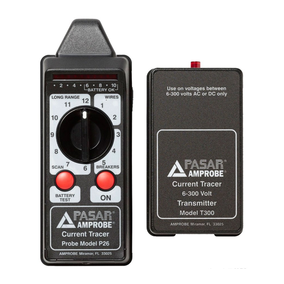
Amprobe CT-326-C Benutzerhandbuch - Seite 12
Blättern Sie online oder laden Sie pdf Benutzerhandbuch für Messgeräte Amprobe CT-326-C herunter. Amprobe CT-326-C 20 Seiten. Current tracer
Auch für Amprobe CT-326-C: Handbuch (2 seiten)

Neutral Lines within a breaker Panel
Neutral lines may also be traced since the magnetic signal produced by the transmitter returns
on the circuit's neutral line.
Follow steps 1-15
16. With the panel trim removed and the receiver's range switch set on "Wires-1," touch the
receiver's tip to the neutral wires in the breaker panel. The receiver will indicate only on the
neutral of the circuit to which the Transmitter is attached.
Phases, Main breakers, Transformers, Switch Gear. 300 V Max.
Since the Transmitter signal is current drawn from the power line, it will travel from the
transmitter to the source of power and back on the circuit's "hot" and neutral lines, totally
unaffected by distance. Therefore, the receiver will be able to detect the phase that bears the
circuit to which the transmitter is attached, i.e., the remote main breaker, the utility box, the
transformer, the switch gear, etc. These do not have to be in the same building or on the same
floor as the location of the circuit where the transmitter is attached.
As the transmitter's signal passes through transformers, it is affected only by the step-up or
step-down ratio of the transformer. For example, if the signal passes through a 2:1 step-down
transformer, the signal will be reduced by one half.
When tracing the path of the circuit through transformers, it may be necessary to set the
receiver's range switch to a "Long Range" position.
1.800.561.8187
Fig.3 Correct the angle of the probe for
accurate readings
10
www.
.com
Fig.4
