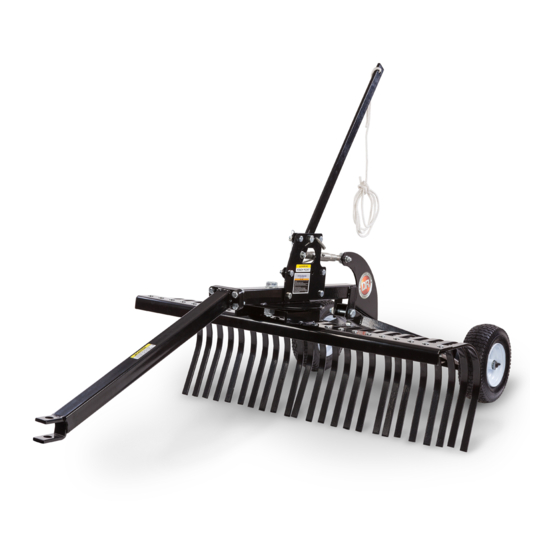
DR 48" LANDSCAPE RAKE Sicherheits- und Betriebsanleitung - Seite 8
Blättern Sie online oder laden Sie pdf Sicherheits- und Betriebsanleitung für Rasen- und Gartengeräte DR 48" LANDSCAPE RAKE herunter. DR 48" LANDSCAPE RAKE 16 Seiten.

Chapter 3: Operating The DR 48" LANDSCAPE RAKE
It may be helpful to better familiarize yourself with the features of your Landscape Rake by reviewing Figure 1 in Chapter 2 before
beginning the steps outlined in this chapter.
Operating Safety
Never allow anyone to operate the DR Landscape Rake without first reading and understanding all instructions in this
manual. Be thoroughly familiar with the controls and the proper use of your Landscape Rake before using.
Never let people ride on the Landscape Rake.
Always check for objects in the Landscape Rake's path before moving.
Operating Parameters
The DR Landscape Rake can be used with a Garden Tractor/Lawn Tractor, ATV, UTV, or Utility Tractor. NEVER operate the DR
LANDSCAPE RAKE with a Car or Truck (2WD or 4WD). Use of these vehicles can be hazardous and will void the DR LANDSCAPE
RAKE Warranty.
Height
Operate
Adjust
Link
Figure 9
Figure 10
®
DR
8
48" LANDSCAPE RAKE
Transport Position
Transport
The Landscape Rake is in the Transport position when the weight of the
machine is supported by the wheels and the tines are lifted from the ground.
This allows the Landscape Rake to be transported to and from the working area
Lift
without the Tines touching the ground. To position the Landscape Rake in the
Handle
transport position, pull forward on the Nylon Rope/Lift Handle (Figure 9). To
lock the machine in the Transport Position, pull forward on the Lift Handle and
Insert the Hitch Pin and Retaining Pin into the Lift Handle Support.
Operating Position
Hitch Pin and
Retaining Pin
The Landscape Rake is in the operating position when the wheels are lifted and
the Tines are on the ground. This allows the tines to scrape, grade, and
resurface the soil when towed behind a tow vehicle. To position the Landscape
Rake in the operating position, pull forward on the Lift Handle and remove the
Hitch Pin and Retaining pin, then slowly release the Lift Handle so that the tines
are lowered to the ground (Figure 9).
Hitch Pin and
Retaining Pin
Frame
Adjusting the Height
Adjust the Height of the Transport/Operating Positions by turning the Height
Adjust Link (Figure 9).
Adjusting the Rake Angle
Tine Assembly
While Locked in the Transport Position, Remove the Hitch Pin and Retaining Pin
that Locks the Tine Assembly to the Frame (Figure 10). Rotate the Tine
Assembly to the desired angle and replace the Hitch Pin and Retaining Pin.
Do not exceed 5MPH when using the DR Landscape Rake in the
Operating Position.
Do not exceed 10MPH when using the DR Landscape Rake in the
Transport Position.
