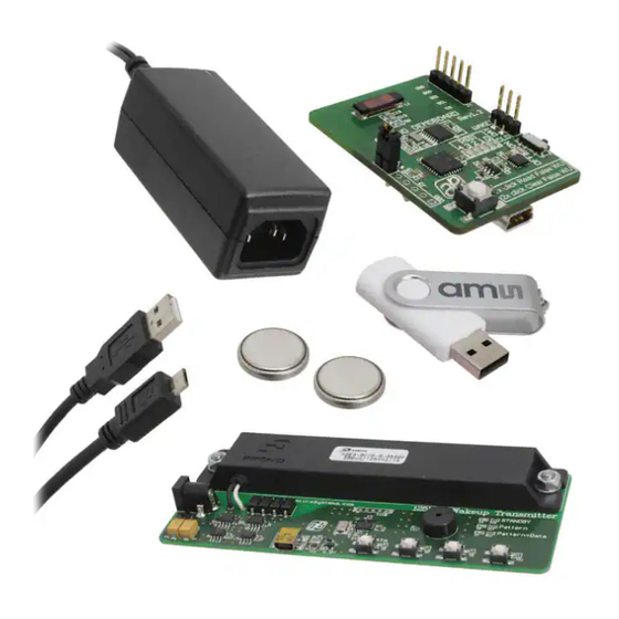
AMS AS3930 Handbuch - Seite 7
Blättern Sie online oder laden Sie pdf Handbuch für Hauptplatine AMS AS3930 herunter. AMS AS3930 19 Seiten. Standard board, demo kit

AS3930 Standard Board
Label
Name
C
AUTO
D
STOP
E
USB-Connector
F
Power Supply
Figure 6: Indication LEDs/Buzzer
LEDs
Blinking Color
G
Buzzer
STANDBY
Red LED
Pattern
Red LED
Pattern+Data
Red LED
:
Note
Before the 125 kHz Wake-up Transmitter is connected to the GUI via USB it is necessary to stop transmitting Wake-
up Patterns by pressing the button "D".
4
Software Description
4.1
Install the GUI
Execute the AS393x_EvalSW_v2.1.6b.msi which can be found on the USB stick in the folder
'Software_Firmware'
Follow the installation guide
Run the GUI AS393x_EvalSW.exe
Attach the respective board ( Demo Board or Transmitter Board ) with the USB cable
From the pop up window 'Choose Plugin' choose the 'AS3932_plugin.dll'
Figure 7: Plugin selection
Note: Before connecting the 125 kHz Wake-up Transmitter Board with the USB cable press "D" to stop transmitting wake-up
patterns.
ams Demo Kit Manual, Confidential
[v1-02] 2014-Jul-10
Description
Automatic Pattern –
Button
Stop Pattern – Button
Mini USB 5-pin
Connector
+9V DC Power Supply
(2A)
Info
Whenever a wake-up pattern is transmitted the buzzer
signals shortly. The buzzer can be disabled via the GUI.
Transmitter is on standby. No wake-up pattern is sent.
Wake-up pattern is transmitted
Wake-up pattern plus data is transmitted
Info
Pressing this button the transmitter
automatically sends a wake-up
pattern every 1s
This button stops sending the
continuous wake-up pattern
USB Interface for the GUI
Insert power adapter here.
Document Feedback
Page 7
