AMS AS5600 Betriebshandbuch - Seite 8
Blättern Sie online oder laden Sie pdf Betriebshandbuch für Kontrolleinheit AMS AS5600 herunter. AMS AS5600 10 Seiten. 12-bit programmable contactless potentiometer
Auch für AMS AS5600: Betriebshandbuch (12 seiten), Handbuch (14 seiten), Benutzerhandbuch (13 seiten)

AS5600-SO_EK_AB
Operation Manual
Note1: Supply
J1=OPEN: 5V
J1=CLOSED: 3.3V
VDD
J1
not populated
C1
C0603
100nF
1740614
Farnell
GND
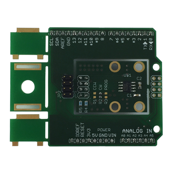
4.2 Layout and Board Dimensions
The PCB layout is shown below in
Figure 6:
Adapterboard layout
4.3 Bill of Materials
The BOM of the pcb is below in
Table 3:
Bill of Materials
Designator
J1
J2
J3
R1
R2
R3
C1
C2
www.ams.com
Arrow.com.
Arrow.com.
Arrow.com.
Arrow.com.
Arrow.com.
Arrow.com.
Arrow.com.
Arrow.com.
Downloaded from
Downloaded from
Downloaded from
Downloaded from
Downloaded from
Downloaded from
Downloaded from
Downloaded from
Note3: Direction
Note2: PGO
R2=NC: Normal Operation
R1=NC/R3=0R: CW
R2=0R: Programming Option
R1=0R/R3=NC: CCW
C2
C0805
R3
10uF
NC
1833804
Farnell
GND
GND
Figure
Table
Part
Jumper / not populated
Header / not populated
Header / not populated
Resistor / not populated
0R
Resistor / not populated
C0603
C0805
Note4: Optional pull-ups
VDD
VDD
VDD
R4
R5
R1
NC
NC
NC
R2
0R
2008343
GND
6.
3.
Footprint
Manufacturer
R0603
R0603
R0603
0603
0805
Revision 1.0 / 05.05.2014
Note5:
Adapterboard can be used with AS5XXX-UCB-1.0
(Use 4pin I2C header in 3.3V mode)
Note6:
AS5600 I2C Address is 0x36h
Comment
clockwise direction default
page 8/10
