AMS AS5601 Handbuch - Seite 7
Blättern Sie online oder laden Sie pdf Handbuch für Adapter AMS AS5601 herunter. AMS AS5601 13 Seiten. Usb interface & programming box
Auch für AMS AS5601: Betriebshandbuch (12 seiten), Benutzerhandbuch (13 seiten)

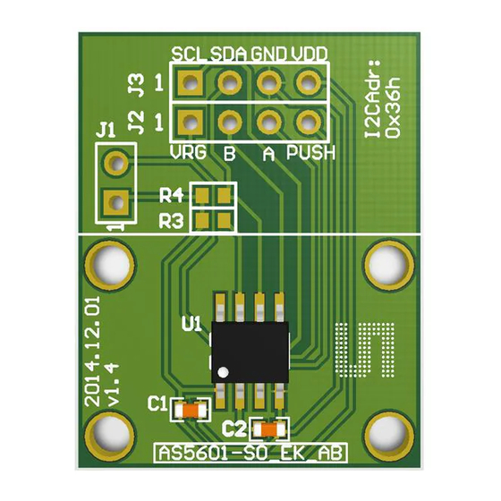
AS5601 Adapter Board
Figure 5:
Aligning electrical and mechanical grid
Mechanical
position 8
Mechanical
position 7
Mechanical
position 6
If the electrical are mechanical grid are not aligned due to production, it can easily be configured
using a grid offset. The grid offset is calculated as shown below:
=
... [ ]
... [°]
Note: To configure the grid offset, the offset value in degrees must be converted and written into
the ZPOS register.
6.2 Configuring the grid push button threshold
The push-button threshold must be configured for optimal output. Therefor the threshold must be
determined and written into the PUSHTHR register.
The swing of the pushbutton function can be found by subtracting the AGC value of the pressed
button from the AGC value of the released button. The threshold value for the contactless
pushbutton should be half of the swing.
6.3 Permanently programming a configuration
A configuration is written using the I2C interface. The Burn_Setting command (Write 0x40 into
register 0xFF) can be used to permanently program a configuration.
6.3.1 Low Power Mode
Three low power modes are available to reduce the power consumption down to 1,5mA max.
ams Eval Kit Manual, Confidential
[v1-00] 2014-Jul-31
Mechanical
position 1
Electrical
Electrical
pos ition 1
pos ition 2
Electrical
pos ition 8
Electrical
pos ition 7
Electrical
Electrical
pos ition 6
pos ition 5
Mechanical
position 5
(;
Mechanical
position 2
Electrical
pos ition 3
Mechanical
position 3
Electrical
pos ition 4
Mechanical
position 4
360°
360°
) −
2
2 ∗ 2
Page 7
Document Feedback
