Draper Acumen E Anleitung Installation & Betrieb - Seite 3
Blättern Sie online oder laden Sie pdf Anleitung Installation & Betrieb für Projektionsfläche Draper Acumen E herunter. Draper Acumen E 12 Seiten. Electric projection screen 220v
Auch für Draper Acumen E: Anweisungen für Installation und Betrieb (12 seiten)

Acumen
XL E & V
™
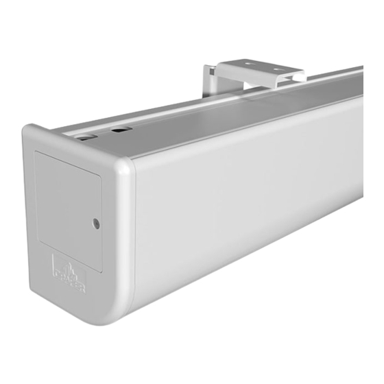
Section 2 - Fascia Removal
MUST BE DONE PRIOR TO REMOVAL OF SHIPPING BRACKETS
To remove fascia:
1. Remove the screws from bottom from lip at each end of the fascia using 3/32" hex wrench.
2. Lift fascia off of the top lip of the case spine extrusion.
To install fascia:
1. Hook the top lip of fascia over the top lip of spine extrusion.
2. Push bottom edge of fascia towards the case spine.
3. Align holes in fascia with end cap holes and screw in
the attachment screw using 3/32" hex wrench.
Section 3 - Removing Shipping Brackets
Screen should not be operated until after dowel shipping brackets are removed
Please Note: Before fully operating screen: lower viewing surface enough to fully expose shipping brackets, then remove shipping brackets See Fig. 1 below.
MEDIUM DOWEL
2 1/ 8 " (54mm)
FRONT
VIEW
1
Remove ½"
hex bolts
(13mm)
securing
"green"
brackets
to the
"gold"
brackets
attached to dowel.
LARGE DOWEL
3 ½" (89mm)
FRONT
VIEW
1
Remove ½"
hex bolts
(13mm)
securing
"green"
brackets
to the
"gold"
brackets
attached to dowel.
Section 4 - Operation
110-120V Single Station Control — 3-position up-off-down switch permits operation to be stopped at any point.
Factory adjusted limit switches automatically stop screen when fully down or fully up.
For LVC-IV Controls:
24V Control — Three-button up-stop-down switch
when fully down or fully up.
1. Key-operated power supply switch controls power to unit and switches. When "off", switches will not operate. Key may be removed in either "on" or "off" position.
2. A three-position key switch permits screen to be operated directly by key. In this case, screen operator must always have a key.
RS232 / Ethernet — Serial communication and network communication available.
(Tab-Tensioned Screens Only)
Figure 2-A
Roller
Bracket
Ro lle r
SC RE EN
DO WE L
2
Remove ½"
(13mm)
carriage bolts
securing
SC RE EN
brackets to the roller brackets.
DO WE L
Figure 2-B
R ol le r
SC RE EN
DO WE L
2
stop at any point desired, operate in any sequence. Factory adjusted limit switches automatically stop screen
(es)
1
1
Figure 1-B
Roller
Bracket
BACK
VIEW
3
hex bolts
and
Lower screen surface down some
"green"
and remove the
"gold"
brackets
from the dowel.
Retighten the
dowel screws.
SC RE EN
DO WE L
3
Remove ½"
hex bolts
and
Lower screen surface down some
(13mm)
carriage bolts
securing
"green"
and remove the
brackets to the roller brackets.
from the dowel.
Retighten the
page 3 of 10
2
Figure 1-A
3
2
BACK
VIEW
"gold"
brackets
dowel screws.
