Bosch 800 Series Installationsanleitung Handbuch - Seite 12

Blättern Sie online oder laden Sie pdf Installationsanleitung Handbuch für Backofen Bosch 800 Series herunter. Bosch 800 Series 40 Seiten. Built-in wall ovens
Auch für Bosch 800 Series: Installationsanleitung Handbuch (24 seiten), Installationshandbuch (40 seiten), Handbuch für Gebrauch und Pflege (12 seiten), Installationshandbuch (23 seiten), Installationshandbuch (28 seiten), Installationshandbuch (32 seiten), Gebrauchsanweisung (32 seiten), Installationshandbuch (32 seiten), Schnellstart- und Sicherheitshandbuch (7 seiten), Handbuch für Gebrauch und Pflege (40 seiten), Installationshandbuch (40 seiten), Installationshandbuch (32 seiten), Installationshandbuch (48 seiten), Handbuch für Gebrauch und Pflege (33 seiten), Handbuch für Gebrauch und Pflege (49 seiten), Schnellstart-Handbuch (7 seiten), Schnellstart- und Sicherheitshandbuch (13 seiten), Installationshandbuch (32 seiten), Service-Handbuch (36 seiten), Installationsanleitung Handbuch (29 seiten), Handbuch für Gebrauch und Pflege (24 seiten), Handbuch für Gebrauch und Pflege (40 seiten), Installationsanleitung Handbuch (28 seiten)
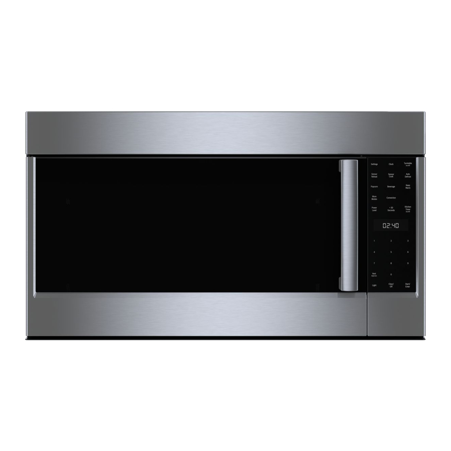
Bosch 800 Series Installationsanleitung Handbuch

Connect Electrical Supply

WARNING
9
RISK OF ELECTRIC SHOCK
Before wiring the appliance, interrupt the main
electrical circuit at the electrical control cabinet. A
circuit with 120 VAC, 15 or 20 Ampere is required.
Grounding notes: this appliance is equipped with a
distributor box with 3 cables. Use the green-yellow
cable for grounding the appliance. Connect the
green-yellow cable to the grounding cable on the
house connection to prevent electric sthock. Do not
under any circumstances damage or remove the
green-yellow cable. Non-adherence can cause
deadly injuries or electric shock.
Installation work and electrical wiring must be done
by qualified person(s) in accordance with all
applicable codes and standards, including
fire-rated construction.
Remove the left cable passage and the cover of the
1.
motor controller. Fasten the connecting piece for the
installation pipe (listed in cULUS) to the cable
passage.
A
Cable passage
B
Cover of the motor controller
2.
Connect 1/2" (12.7 mm) installation pipe to motor
controller.
A
Installation pipe
B
Power connection
C
Cable connector listed in UL
12

Attaching flue duct

Hidden surfaces may have sharp edges. Use caution
when reaching behind or under appliance.
1.
Remove the protective foil from both flue ducts.
2.
Push one flue duct into the other.
Notes
To prevent scratches, lay paper over the edges of
the lower flue duct to protect the surface.
For ducted operation, turn the upper flue duct so
that the ventilation slots point downward.
Remove the protective foil from the extractor hood.
3.
Place flue ducts on the appliance.
4.
5.
Push the inner flue duct upwards and attach it to the
angle brackets on the left and right.
6.
Screw the flue duct to the sides of the angle bracket
using two screws.
A
Upper flue duct
B
Lower flue duct
C
Screws
D
Angle bracket