AirStage UTY-RNKYT Installationshandbuch - Seite 6
Blättern Sie online oder laden Sie pdf Installationshandbuch für Controller AirStage UTY-RNKYT herunter. AirStage UTY-RNKYT 8 Seiten. Wired remote controller
Auch für AirStage UTY-RNKYT: Betriebshandbuch (13 seiten)

7. TURNING ON THE POWER
Recheck the wiring. Incorrect wiring will cause trouble.
(1) Check the remote controller wiring and DIP switch settings.
(2) Install the front case.
* When installing the front case, connect the connector to the front case
(in 5 INSTALLING THE REMOTE CONTROLLER).
(3) Check the indoor and outdoor unit wiring and circuit board switch
settings, and then turn on the power of the indoor and outdoor units.
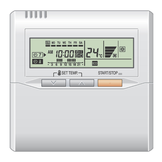
After "
" has fl ashed on the set temperature display for several
seconds, the clock display will appear in the center of the remote
controller display.
*
For the wiring and circuit board switch settings method, refer to the
installation manual for the indoor unit and outdoor unit.
8. SETTING THE ROOM TEMPERATURE
DETECTION LOCATION
As the temperature sensor of remote controller detects the temperature
near the wall, when there is a certain difference between the room
temperature and the wall temperature, the sensor will not detect the
room temperature correctly sometimes. Especially when the outer side
of the wall on which the sensor is positioned is exposed to the open air,
it is recommended to use the temperature sensor of the indoor unit to
detect the room temperature when the indoor and outdoor temperature
difference is signifi cant.
The detection location of the room temperature can be selected from the
following 2 methods. Choose the detection location that is best for the
installation location.
The temperature sensor of the indoor unit or the remote controller can be
used to detect the room temperature.
Press the "
more to select the temperature sensor of the indoor unit or the remote con-
troller.
NOTES
The remote controller sensor cannot be used if the indoor unit has no
temperature setting function. When this function cannot be used, the lock
display
will fl ash when the "
button is pressed.
9. ADDRESS SETTING
Address setting method of indoor unit can be selected from 3 options (outdoor
unit, indoor unit and remote controller).
Refer to the installation manual of outdoor unit or indoor unit when set up
from the outdoor unit or the indoor unit.
•
"Indoor unit address" and "Refrigerant circuit address" can be set using
the remote controller.
•
This function can be set in all indoor units when the remote controller is
connected.
•
"Remote controller address" cannot be set in this function.
Ensure to set with the Rotary switch of PCB of the indoor unit.
•
When setting the address of indoor unit, refer to installation manual of
indoor unit.
En-5
CAUTION
CAUTION
" button for 2 seconds or
Indoor unit
•
When setting the address of outdoor unit automatically, refer to installation
manual of outdoor unit.
•
When setting the address with a remote controller, refer to installation
manual of indoor unit for setting details of indoor unit.
Switching selection of address setting mode
(1) Press the "
"
" button for more than 5 seconds simultaneously. Then shift to
Address setting mode.
Indoor unit address setting
(2) Press the "
address (Select the relevant indoor unit).
(3) The Address code "01" blinks when pressing the "
"
" button.
(4) Set the Indoor unit address data by pressing the "
button or "
(5) Fix the Indoor unit address data by pressing the "
(Data is transferred to the indoor unit).
PROHIBITED
"
•
When Indoor unit address data is
not set in the indoor unit address.
(-- is displayed).
•
Set the Indoor unit address data
again as per procedure (3)-(5)
above.
" button, "
Address setting mode initial display
" button and select the Remote controller
Remote controller address
Ex. When Remote controller
address "01" is selected.
" button or
Address code
" button. (Range of setting is 00-63.)
Indoor unit address data
Ex. When Indoor unit address data
"12" is selected.
GOOD
When Indoor unit address data
is set in the indoor unit properly.
(Blinking changes to steady illumi-
nation)
" button and
"
" button.
