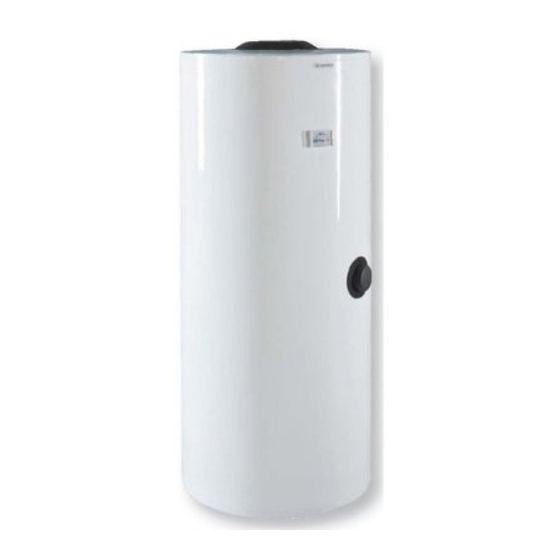
Drazice OKC 200 NTRR/SOL Betriebs- und Installationshandbuch - Seite 7
Blättern Sie online oder laden Sie pdf Betriebs- und Installationshandbuch für Warmwasserbereiter Drazice OKC 200 NTRR/SOL herunter. Drazice OKC 200 NTRR/SOL 12 Seiten. For solar systems
Auch für Drazice OKC 200 NTRR/SOL: Betriebs- und Installationshandbuch (17 seiten)

Tank volume (except anode and exchanger)
Tank volume
Diameter of the heater
Weight
Max. operational overpressure in the tank
Max. operational overpressure in the exchanger
Max rating water temperature
Max temperature of HSW
Upper exchanger heat delivery surface
Lower exchanger heat delivery surface/
Rated lower exchanger output with temeperature gradient 80/60°C
Rated upper exchanger output with temeperature gradient 80/60°C
Continuous HUW* power of lower exchanger output with
Continuous HUW* power of upper exchanger output with
Rated lower exchanger output with temeperature gradient 60/50°C
Rated upper exchanger output with temeperature gradient 60/50°C
Continuous HUW power of lower exchanger output with temeperature
gradient 60/50°C
Continuous HUW power of upper exchanger output with temeperature
gradient 60/50°C
Performance number ac. to DIN 4708 upper exchanger
Performance number ac. to DIN 4708 lower exchanger
Heating period for HUW* with a lower exchanger with temperature
gradient 80/60°C
Heating period for HUW* with a upper exchanger** with temperature
gradient 80/60°C
Heating period for HUW* with a lower exchanger with temperature
gradient 60/50°C
Heating period for HUW with a upper exchanger** with temperature
gradient 60/50°C
Heat losos
*HSW -hot utility water 45°C
** heating of tank volume, which is appropriate to upper exchanger
6. EXAMPLES OF HEATERS CONNECTION
Connecting a heater to a solar system:
Heater shall be connected to a solar system by a person familiarised with these heating systems.
Temperatures in a solar circuit may achieve far over 100°C, and there are higher pressures than in
typical heating systems, therefore correct selection of interconnecting materials and its coupling is of
great importance, as well as correct dimensioning of the expansion tank connected to this system.
The heater is placed on the ground, next to the heating source, or in its vicinity. The heating circuit is
connected to marked inputs and outputs of the heater exchanger; the deaerating valve designed for solar
system is mounted in the highest place. It is recommended to flush the heating circuit before the assembly.
All wiring connections must be properly insulated from heat.
Connection of heater:
The manufacturer recommends mounting of a mixing valve on the hot water outlet, on sunny days the
temperature in the heater can achieve up to 90°C which is a temperature that, in case of scalding, may cause
health complications. Output temperature suitable for common use shall be set on the mixing valve.
Cold water shall be connected to an inlet marked with a blue ring or writing "HSW INLET". Hot water shall be
connected to an outlet marked with a red ring or writing "HSW INLET". If the hot service water (HSW) distribution is
equipped with circulation circuit, it shall be connected to the outlet marked with "CIRCULATION". For potential
Type
OKC 400
NTR/SOL
l
395
l
378
mm
650
kg
119
Mpa
1
MPa
1
°C
110
°C
95
m2
-
m2
2
kW
58
kW
-
l/h
1423
l/h
-
kW
25
kW
-
l/h
767
l/h
-
NL
-
NL
-
min
23
min
-
min
42
min
-
kWh/24h
7
OKC 400
OKC 500
NTRR/SOL
NTR/SOL
NTRR/SOL
395
467
369
449
650
700
137
135
1
1
1
1
110
110
95
95
1
-
2
2
58
59
26
-
1423
1448
638
-
25
26
12
-
767
797
368
-
-
-
-
-
22
27
22
-
41
48
38
-
OKC 500
467
436
700
160
1
1
110
95
1,4
2
59
37
1448
908
26
18
797
552
-
-
26
17
47
27
