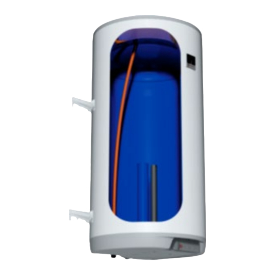
Drazice Okce 100 Betriebs- und Installationshandbuch - Seite 10
Blättern Sie online oder laden Sie pdf Betriebs- und Installationshandbuch für Warmwasserbereiter Drazice Okce 100 herunter. Drazice Okce 100 19 Seiten. Tank-type water heater for vertical
mounting
Auch für Drazice Okce 100: Betriebs- und Installationshandbuch (18 seiten), Betriebs- und Installationshandbuch (16 seiten)

Universal suspension
The use of the suspension even for the screw spacing during the replacement with a heater of another type.
The heater verticality after the release of the connecting screws can be aligned by means of slight turning.
If the hot water heater is mounted in a tight, small space, or in an intermediate ceiling, etc., you
have to make sure that the connecting side of the appliance (connections to water supply, area
for electric plugging) remained accessible and no heat accumulation occurs. Free space of up to
600 mm from the bottom edge of the heater has to be available under the heater.
When mounted directly under the ceiling, the distance from the ceiling has to be
50 mm at least.
If the water heater is mounted in enclosed areas, inter-ceilings, built-in structures and recesses,
ensure sufficient access to service fittings, electrical terminal boards, anodes and manholes.
Minimum spacing from manhole is 600 mm.
2.3 PLUMBING FIXTURE
The heater connects to water distribution tubes with G1/2" thread in the bottom part of
the heater. Blue - cold water supply, red - hot water outlet. For potential disconnection of
the heater, the service water inlets and outlets must be provided with screw coupling Js 1/2".
The safety valve is mounted on the cold water inlet identified with a blue ring.
The heater must be equipped with a membrane, spring-loaded safety valve. Safety valves with
fixed pressure settings from the manufacturer are used for the assembly. Each individually
lockable heater must be fitted with a cap on the cold water inlet, a test valve or a stopper
to check the operation of the check valve, with a check valve and a relief valve (Figure 6).
The safety valve with a check valve is supplied with the heater.
Figure 5
- 10 -
