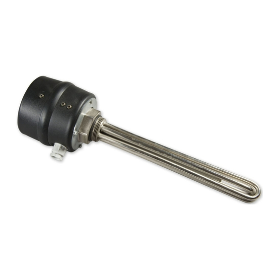
Drazice TJ 6/4“ - 3.75 Betriebs- und Installationshandbuch - Seite 4
Blättern Sie online oder laden Sie pdf Betriebs- und Installationshandbuch für Warmwasserbereiter Drazice TJ 6/4“ - 3.75 herunter. Drazice TJ 6/4“ - 3.75 8 Seiten. Screw-mounted electrical heating unit

1 PRODUCT TECHNICAL SPECIFICATION
1.1 FUNCTION DESCRIPTION
The screw-mounted electrical heating unit (heating unit) is designed exclusively for water heating. It is
designed as an additional heating source in water heaters connected in a system with solar collectors. It can
also be used as an additional source of heating in accumulation tanks. If the installation requirements are
obeyed, it can be used as the main source of heating by a heater, or for other purposes. It is not intended
for use in stainless tanks. Types with extended cooling compartment can be used in accumulation tanks
marked with v6 and v7.
Water is heated by tubular heating element. Thermowell contains sensors of a safety fuse and a thermostat
(both devices are in a single block). The thermostat controls the set temperature of water. In case of
a failure, the safety fuse switches off electricity supply in all poles within the temperature range of 0 – 90°C.
1.2 ADVICE FOR CUSTOMERS
Prior to putting the heating element into operation, re-measuring of insulation resistance
is recommended. The insulation resistance in cold must not be below 50 MΩ. If the
insulation resistance is lower, we recommend drying the heating element.
Both electric and water installation must follow and meet requirements and regulations
relevant in the country of use.
1.3 DESIGN AND GENERAL HEATER DIMENSIONS
The heating unit consists of an electrical heating element with a connecting thread G 6/4".(Figure 2)
A thermostat and a safety fuse; the element's operation control light; and a connecting terminal board are
placed under the wiring plastic cover Chyba! Nenalezen zdroj odkazů. To use the OKC ... NTR, NTRR, OKCE
... NTR, NTRR heaters in solar systems with reheat by means of electricity, the heaters have a G 6/4" neck
placed for mounting a secondary electrical heating unit. The heating unit is placed above the lower
exchanger.
Thermostat button
Electrical wiring cover
Figure 2
Heating element
Thermostat control
Figure 1
Control light
- 4 -
