CommScope 360-iP-PMAX-GS3-24 Anleitungsblatt - Seite 2
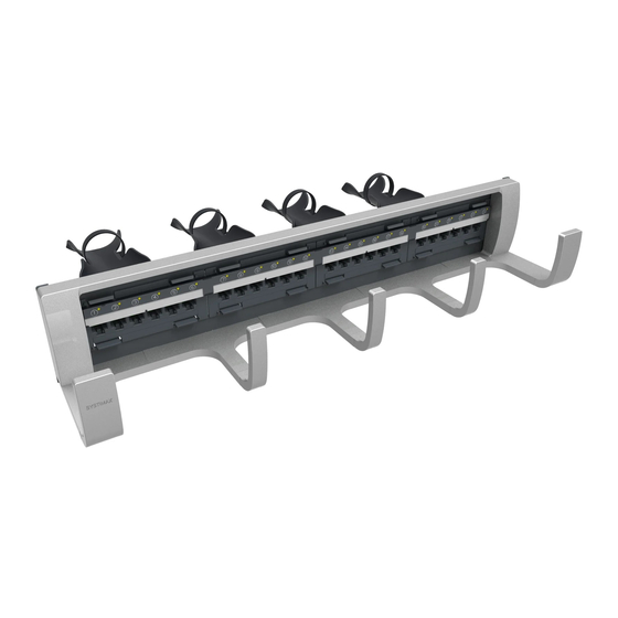
Blättern Sie online oder laden Sie pdf Anleitungsblatt für Kabel und Anschlüsse CommScope 360-iP-PMAX-GS3-24 herunter. CommScope 360-iP-PMAX-GS3-24 6 Seiten. Modular panel
Important Safety Instructions
To reduce the risk of fire, electric shock, and injury to persons, read,
understand, and adhere to the following instructions as well as any
warnings marked on the product.
!
CAUTION
Remote risk of electric shock. Never install the product in wet
locations or during lightning storms. Never touch uninsulated
communication wires or terminals.
Also, follow the precautions below:
All wiring that connects to this equipment must meet applicable
local and national building codes and network wiring standards
for communication cable.
Care should be taken not to compromise the stability of the rack
by installation of this equipment.
SYSTIMAX 360 iPatch PATCHMAX shelves use infrared
Important:
sensing technology and should be installed where they are not
exposed to direct sunlight or other infrared sources.
Save these instructions.
Specifications
Wire Termination
Wire Size:
22–24 AWG (0.64–0.51 mm) solid copper
22–24 AWG (0.64–0.51 mm) 7-stranded copper
Insulation Size:
0.042 inch (1.07 mm) maximum DOD
Insulation Type:
All plastic insulants
(including polyethylene, polypropylene, and FEP)
Reterminations
IDC Contact:
200 minimum
Modular Jack:
750 minimum
Environmental Data
º
º
Temperature
-40
F to 158
º
º
Range:
23
F to 122
F (-5
Humidity:
Up to 95% noncondensing
Mounting the Panel
To mount the panel:
1 Remove power from the rack's Panel Manager.
2 The panel is shipped with the cabling labels for B wiring already
installed. If the installation uses A wiring, insert the cabling labels
for A wiring in the slots on the back of the panel. Make sure that
the labels are oriented with the right side up (Figure 1).
Figure 1 Inserting the Cabling Label
Instruction Sheet: SYSTIMAX 360™ iPatch
º
º
F (-40
C to 70
C) (storage)
º
º
C to 50
C) (operational)
Cabling label
3 Install the panel on the rack using the 4 screws provided
(Figure 2). Be careful not to pinch the panel bus jumper(s)
between the panel and rack.
Figure 2 Mounting the Panel
4 Connect the panel bus jumper:
a Remove the adhesive backing from the cable retainers on the
panel bus jumper.
b Connect the panel bus connector on the jumper to the
nearest connector on the panel bus, folding the jumper as
shown (Figure 3). Press the cable retainers against the rack.
Note: The connector is keyed. The polarized tab on the jumper
connector fits into the opening in the header connector on the
panel bus.
For 48-port panels, connect both panel bus jumpers.
Important:
Figure 3 Connecting and Routing the Panel Bus Jumper
Cable
retainer
2
®
®
PATCHMAX
Modular Panel
Mounting screws
Panel bus
Panel bus
jumper
Cable retainer
Polarized tab
Panel bus jumper
Panel bus
Fold the panel bus
jumper as shown.