CommScope FOSC-ACC-B-TRAY-12-RBN Installationsanweisung - Seite 2
Blättern Sie online oder laden Sie pdf Installationsanweisung für Gehege CommScope FOSC-ACC-B-TRAY-12-RBN herunter. CommScope FOSC-ACC-B-TRAY-12-RBN 6 Seiten. Fiber optic splice closure trays: a/b ribbon size
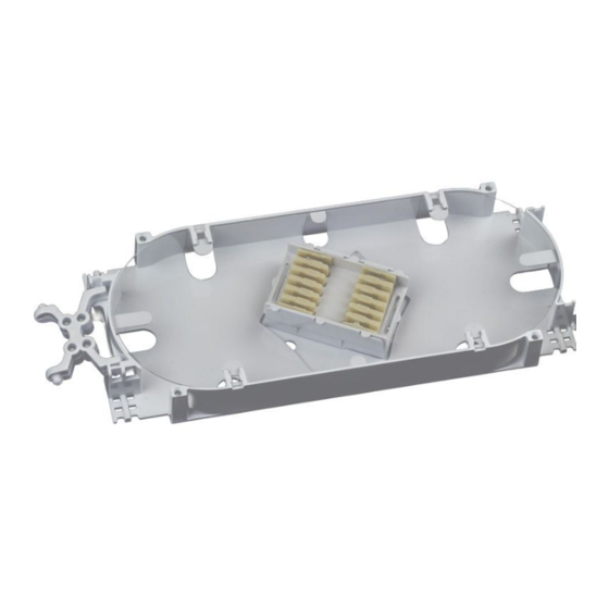
3.2 Tray Kit Information
Tray Kit
A Ribbon Tray Type
FOSC-ACC-A/B-TRAY-12-RBN
A Standard Type
FOSC-ACC-A-TRAY-12
FOSC-ACC-A-TRAY-16
FOSC-ACC-A-TRAY-24
B Ribbon Tray Type
FOSC-ACC-A/B-TRAY-12-RBN
B Standard Type
FOSC-ACC-B-TRAY-12
FOSC-ACC-B-TRAY-16
FOSC-ACC-B-TRAY-24
1 Requires storage of ribbon slack in closure slack basket.
2 CommScope SMOUV splice sleeves are highly recommended in these applications.
4.0 Attach Ribbon to Tray
1.
Prepare the main cable, strength member(s) and ribbon
bundles in accordance with the procedures in the appro-
priate closure installation instructions for your application.
2.
Install spiral or ribbon transportation tubing (in closure kit).
3.
Install ribbon holder:
a.
For 24- ber ribbons, lay the ribbon bundle in the
ribbon holder as shown in Figure 1A.
Note: Ribbons will need to be split into two 12- ber rib-
bons.
b.
For 12- ber ribbons, fold down the appropriate
number of spacers as shown in Figure 1C. Use the
following chart to determine the number of spacers to
fold down:
Number of
Ribbons
24
12
6 or less
c.
Stand the ribbons on end as shown in Figure 1B.
d.
Once the ribbons are in the ribbon holder, fold the top
of the ribbon holder over and snap it closed.
e.
Slide the ribbon holder into the spiral tubing.
Q
u
a
n
i t
y t
y T
p
e
f o
of Modules
Module Included
in Tray Kit
in Tray Kit
2
SM-6 Modules
2
SM-6 Splice Modules
2
SM-8 Splice Modules
2
SM-12 Splice Modules
2
SM-6 Splice Modules
2
SM-6 Splice Modules
2
SM-8 Splice Modules
2
SM-12 Splice Modules
Number of
Spacers
0
2
3
S
p
i l
e c
Splice Types
Accommodated
Mass Fusion
Single Fusion
Single Mechanical
Mass Fusion
Single Fusion
Single Mechanical
Single Fusion
Mass Fusion
Single Fusion
Single Mechanical
Mass Fusion
Single Fusion
Single Mechanical
Single Fusion
C
2
M
a
. x
Q
t
. y
f o
Splices Accommodated
per Tray
12
12
12
12
1
8
8
24
2
12
12
12
12
1
8
8
24
2
Ribbon Holder
Figure 1