Comnet FVR1010SHR Installations- und Betriebshandbuch - Seite 7
Blättern Sie online oder laden Sie pdf Installations- und Betriebshandbuch für Transmitter Comnet FVR1010SHR herunter. Comnet FVR1010SHR 11 Seiten. 8-channel 10-bit digitally encoded video + 8-channel bi-directional data + self-healing ring topologies

INSTALLATION AND OPERATION MANUAL
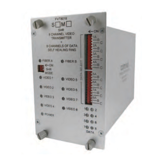
FIGURE 9 – SHR SWITCH POSITIONS
DcH1/SHR Switch
Resulting configuration
1
2
NA*
ON
disable Remote Fault locator (RFl) feature
NA*
OFF
Enable Remote Fault locator (RFl) feature
* Switch 1 on the FVT/FVR8018SHR unit is not used currently and is reserved
for a future release.
FIGURE 10 – LED INDICATORS
OPTIc A/B
GREEN
Communication link has been established
over optical fiber
RED
Communication link has not been
established.
GREEN/RED
Communication has been established
BLINK
over optical fiber. However a fiber break
has been detected in the system.
OFF
Unit powered down
Remote Fault Locator (RFL) using the OPTIc LEDs
The bi-color oPTIC A and oPTIC b lEds on the front panel convey the status of the optical link between one unit and the next unit around the ring, as well as
the status of the ring as a whole. They can be used to identify the location of a remote fiber fault based on their color and pattern:
• Solid Green
Optical link has been established between this optical port and the adjacent unit over fiber.
Furthermore, every other unit in the system is also reporting that link has been established.
There are no faults in the system.
• Solid Red
Optical link over this port has been lost.
This could be due to a broken fiber, a bad connection, or loss of power at the adjacent unit.
• Blinking
Green/Red
Optical link has been established between this optical port and the adjacent SHR unit.
However, a fault condition has been detected somewhere in the system. The oPTIC lEd will be green for a period of time, and
then flash red some number of times. The number of red flashes indicates the location of the fault by "hops" around the ring. If
the lEd flashes red three times, then the location of the fault is three hops away (i.e. three SHR units away). For larger systems
with faults greater than 9 hops away, the lEd will use a combination of long and short red flashes. Each long flash indicates 10
hops. Each short flash indicates 1 hop. For example, a fault 47 hops away would be encoded as 4 long red flashes, followed
immediately by 7 short red flashes. The pattern repeats indefinitely until the fault is resolved.
TEcH SUPPORT: 1.888.678.9427
SHR Switch 2 can disable the Remote Fault locator (RFl) feature of the oPTIC
A and oPTIC b lEds as described in Figure 10. For self-healing ring topologies,
this switch would normally be turned oFF at every unit in the system so that
the RFl is enabled. However, for linear topologies this switch would be turned
oN at the two end points and turned oFF at the rest of the units. disabling the
RFl at these two locations prevents them reporting their disconnected optic
ports as a fault to the rest of the units in the system. Fiber breaks throughout
the rest of the system will still be reported normally, even at the two end-
points. It is also possible to completely disable the RFl by setting this switch to
the oN position at every unit in the system. In this case, the oPTIC A and oPTIC
b lEds will only report the status of the optical link between this unit and the
next; the lEds would either be solid green or solid red.
VIDEO
An active video signal is present on
the bNC connector.
No video signal is present.
–
Unit powered down
DATA
An active data signal is present on the
pins of the data connector.
–
–
No data signal is present.
FVT/FVR8018SHR
POWER
Unit powered up
–
–
Unit powered down
INS_FVT/FVR8018SHR_REVA
11/14/11
PAGE 7
