Bose 251 Handbuch - Seite 2
Blättern Sie online oder laden Sie pdf Handbuch für Redner Bose 251 herunter. Bose 251 8 Seiten. Environmental speakers
Auch für Bose 251: Benutzerhandbuch (29 seiten), Benutzerhandbuch (16 seiten)
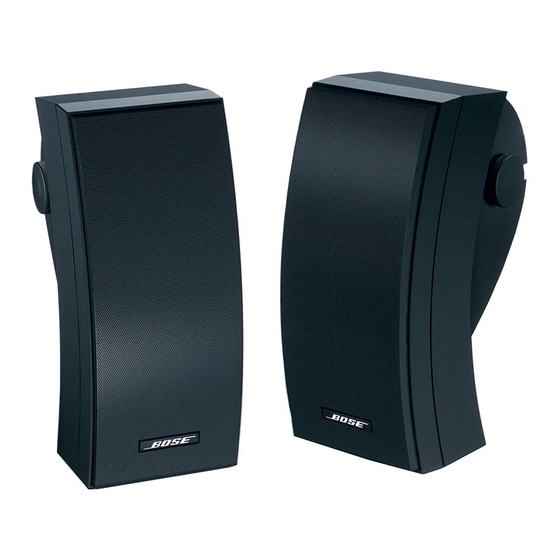
251 Environmental Speaker 256033
The Bose
251™ Environmental Speaker is a premium environmental loudspeaker. Each loud-
®
speaker contains one 5.25" environmentally resistant woofer in a two-chamber configuration, two
2.5" environmentally resistant Twiddlers™ vertically stacked and angled for maximum horizontal
dispersion and a crossover including system protection. The system is packaged with mounting
brackets.
Transducers:
Impedance:
Power Handling:
Crossover Assembly:
System Protection:
Sensitivity:
Flux Leakage:
External Dimensions:
Weight:
1. Grille and Baffle Removal
1.1 Grasp the edge of the grill (5) and pull it
off.
1.2 Remove the six screws (13) that secure
the baffle to the cabinet and then pull off the
baffle.
2. Grille and Baffle Replacement
2.1 To prevent air leaks, apply a new baffle
woofer mount gasket (10). To prevent wire
buzzes, insert the wires into the cabinet's wire
channel. Line up the baffle so that the baffle's
woofer mount fits into the groove in the
cabinet. Replace the six screws (13) that
secure the baffle to the cabinet.
PRODUCT DESCRIPTION
SPECIFICATIONS
One 5.25" environmental woofer per enclosure
Two 2.5" environmental resistant Twiddlers per enclosure
6 Ohms nominal (4.8 Ohms minimum) 20-20 kHz
100W (24.5 Vrms) continuous per IEC 268-5
Recommended amp/receiver power 10-200W per channel.
Crossover frequency: 250 Hz, 10% at 6 dB/octave
System protection: PTC device.
>82 dB SPL (1W, 1M) 400 Hz octave band limited pink noise
NA, not shielded; not for use near a video monitor
13.5" x 5.75" x 8.34" (34.3 x 14.6 x 21.2) cm
7.75 lb. (3.5 kg)
DISASSEMBLY/ASSEMBLY PROCEDURES
(Refer to Figure 3)
2.2 Align the grille (5) with the cabinet so that
the logo (6) is over the Twiddlers (2). Press
the grille into place.
3. Twiddler Removal.
3.1 Perform procedure 1.1.
3.2 Remove the four screws (12) that secure
the Twiddler (2) to the cabinet.
3.3 Lift the Twiddler out and cut the wires as
close as possible to the wire terminal.
Note: Make a note of the wiring configuration.
4. Twiddler Replacement
4.1 Referring to the note taken in 3.3, attach
the wires to the Twiddler (2).
2