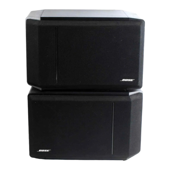
Bose 301 Series IV Service-Handbuch - Seite 4
Blättern Sie online oder laden Sie pdf Service-Handbuch für Redner Bose 301 Series IV herunter. Bose 301 Series IV 12 Seiten. Direct/reflecting speakers
Auch für Bose 301 Series IV: Benutzerhandbuch (12 seiten), Benutzerhandbuch (12 seiten), Benutzerhandbuch (13 seiten)

DISASSEMBLY/ASSEMBLY PROCEDURES
Note: Refer to Figure 3 for the following proce-
dures.
1. Grille Removal: Both the front grille (1) and the
side grille (3) are held in place by a snap-fit and
are easily removed by hand. To remove,
CAREFULLY pull the grille away from the
speaker.
2. Woofer Removal/Replacement:
2.1 Remove the front grille as indicated in Proce-
dure 1.
2.2 Remove the 4 screws (11) holding the woofer
(9) in place.
2.3 Lift the woofer out and cut the wires connected
to the woofer terminals as close to the terminals
as possible.
2.4 Strip the wires and connect to the replacement
woofer. Make sure that the Red wire is con-
nected to the positive (+) terminal, both Black
wires are connected to the negative (-) terminal
and both Yellow wires are connected to the
woofer's "dummy" terminal, (no solder joint at
this terminal). Dress or twist wires to prevent
buzzing.
2.5 Remount the woofer to the cabinet using the
four screws.
3.
3" Tweeter Removal/Replacement: In order
to remove the tweeter it will first be necessary to
remove the woofer from the enclosure.
Note: The positive terminal of the tweeter is
marked with a Red dot.
3.1 Remove both the front and side grilles as
indicated in Procedure 1.
3.2 Remove the 4 screws that secure the woofer to
the enclosure and lift the woofer away from its
opening.
3.3 Remove the #8-32 screw (6) from the back of
the gasket backed tweeter (4) and separate the
tweeter from the molded bracket portion of the
endcap.
3.4 Cut the wires connected to the tweeter as close
to the tweeter terminals as possible.
3.5 Strip the wires and connect the replacement
tweeter. Make sure the Yellow wire is con-
nected to the positive (+) terminal and the Black
wire is connected to the negative terminal (-).
3.6 Remount the tweeter using the #8-32 screw.
3.7 Remount the woofer using the four #8-11
screws.
4. 2" Tweeter Removal/Replacement: In order to
remove the tweeter it will first be necessary to
remove the woofer from the enclosure.
Note: The positive terminal of the tweeter is
marked with a Red dot.
4.1 Remove the front grille only, as indicated in
Procedure 1.
4.2 Remove the 4 screws that secure the woofer to
the enclosure and lift the woofer away from its
opening.
4.3 Remove the #8-32 screw from the back of the
gasket backed tweeter (12) and separate the
tweeter from the molded bracket portion of the
endcap.
4.4 Cut the Yellow wire and the lamp lead con-
nected to the tweeter as close to the tweeter
terminals as possible.
4.5 Strip the Yellow wire and connect the replace-
ment tweeter. Make sure the Yellow wire is
connected to the negative (-) terminal and the
lamp is connected to the positive terminal (+).
Note: To replace just the lamp or both the tweeter
and lamp it will be necessary to remove the tweeter
by following procedures outlined in section 4.
3
