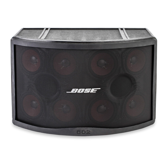
Bose 802 C II Benutzerhandbuch - Seite 11
Blättern Sie online oder laden Sie pdf Benutzerhandbuch für Redner Bose 802 C II herunter. Bose 802 C II 22 Seiten. System controllers
Auch für Bose 802 C II: Service-Handbuch (20 seiten), Service-Handbuch (23 seiten)

Figure 11
The two INPUT jacks.
From balanced
source
+
–
GND
Shield
Figure 12
Connections from a balanced audio source to the
systems controller.
From unbalanced
source
+
–
GND
Shield
Figure 13
Connections from an unbalanced audio source
to the systems controller.
Male XLR
connector
+
Shield
(connected to pin 1)
–
Male XLR
connector
+
Shield (no
connection)
–
5.3 Input Connections
An audio source (mixing console or signal
processor) comes before the systems controller
in the signal path. That audio source feeds the
controller's two INPUT jacks (Figure ).
NOTE: The pin numbers are shown in small type on
the controller's INPUT jacks.
If the audio source has balanced outputs (see Figure
):
1. Find the source's XLR high or plus output pins
(usually pin ). Connect them to the PIN (+)
terminals in the controller's INPUT jacks.
2. Find the source's XLR low or minus output pins
(usually pin 3). Connect them to the PIN 3 (-)
terminals on the controller's INPUT jacks.
3. Connect the source's cable shield to its ground
and to PIN on the controller. (Do not connect it
at the controller input.)
If the audio source has unbalanced outputs (see
Figure 3):
1. Connect the source's high or plus terminals to
PIN (+) on the controller's INPUT jacks.
2. Find the source's ground (-) output terminals
(usually the sleeve on standard /4" jacks).
Connect them to the PIN 3 (-) terminals on the
controller's INPUT jacks. Connect the minus
cable, and NOT the shield, at the controller
inputs.
3. Connect the source's cable shield to the
ground (-) terminal at the source.
