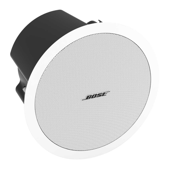
Bose FreeSpace DS 100SE Technisches Datenblatt - Seite 3
Blättern Sie online oder laden Sie pdf Technisches Datenblatt für Redner Bose FreeSpace DS 100SE herunter. Bose FreeSpace DS 100SE 8 Seiten. With ceiling mount bracket
Auch für Bose FreeSpace DS 100SE: Benutzerhandbuch (32 seiten), Installationshandbuch (17 seiten), Installationshandbuch (22 seiten), Design-Handbuch (4 seiten), Service-Handbuch (21 seiten)

FreeSpace
®
DS 100SE
Loudspeakers
Driver complement:
Two 2.25" (57mm) Twiddler
an Articulated Array
®
loudspeaker design
One 5.25" (133mm) woofer
Construction features:
Enclosure: Injection-molded polypropylene
Grille: Powder-coated steel
Dimensions:
Loudspeaker only:
8.5"D x 15"W x 7"H
(216mm x 381mm x 178mm)
Loudspeaker with bracket:
10.9"D x 15"W x 7"H
(276mm x 381mm x 178mm)
Weight:
Product: 13.4lb (6kg)
Shipping: 16lb (7.3kg)
Package contents:
Loudspeaker, mounting bracket and
installation guide
Finish:
Textured black or white finish with a contoured,
powder-coated steel grille. Both the enclosure
and grille can be painted.
Design Recommendations
When creating a design that uses the FreeSpace
DS 100SE loudspeakers, you should consider
the following:
• Recommended mounting height is between
8 and 26ft (2.4 and 8m).
• Provide at least 20ft (6.1m) of space between
adjacent loudspeakers for typical applications.
• In outdoor applications, do not space the
loudspeakers by more than 50ft (15.2m).
• Generally, the FreeSpace DS 100SE loudspeakers
should be pitched downward between 5 and
15 degrees.
• Maximum SPL for a typical application is
between 91 and 98 dB-SPL.
• Always add 25% headroom to your amplifier to
accommodate various types of program material.
Use the following recommended loudspeaker
spacing guidelines for typical mounting heights
between 12 and 22ft (3.6 and 6.7m), as coverage
requirements and loudspeaker spacing will vary.
®
drivers in
®
Connectors:
The included mounting bracket features a
three-terminal barrier strip. Optional junction
boxes provide a pre-wired ceramic connector
and a thermal fuse for use when required.
Mechanical diagrams:
Coverage
Loudspeaker Spacing Distance
Premium
Standard
Minimum
Total system SPL varies based on the mounting
height, tap setting and room acoustics. For typical
applications, use the chart below to determine
the total SPL.
m
2.4 3.0 3.6 4.2 4.8 5.5 6.1 6.7 7.3 8.0 10.0
Mount
Height
8 10 12 14 16 18 20 22 24 26 32
ft
12.5* 89 88 88 87 86 85 84 83 83 82 80
25
92 91 91 90 89 88 87 86 86 85 83
TAP (W)
50
95 94 94 93 92 91 90 89 89 88 86
100
98 97 97 96 95 94 93 92 92 91 89
*12.5-watt tap available only in 70V mode.
For more detailed information, refer to the
DS 100SE loudspeakers Design Guide.
40ft | 12m
50ft | 15m
55ft | 17m
DS 100SE
3 3
p r o . B o s e . c o m
dB-SPL
O O F F
8 8
