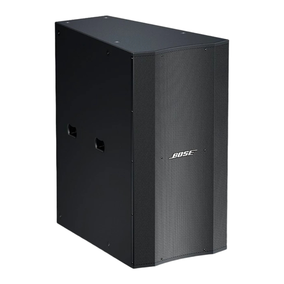
Bose Panaray LT 9402TM WR Service-Handbuch - Seite 21
Blättern Sie online oder laden Sie pdf Service-Handbuch für Redner Bose Panaray LT 9402TM WR herunter. Bose Panaray LT 9402TM WR 27 Seiten. Weather resistant

DISASSEMBLY / TEST PROCEDURES
2. Driver Removal
2.1 Perform procedure 1 above.
2.2 Using a Phillips-head screwdriver, re-
move the 8 screws (5) that secure the driver
(6) to the enclosure.
2.3 Lift the driver out of the enclosure. Make
a note of the wiring configuration and cut the
wires as close to the terminals as possible.
Re-assembly Note: Be sure that the driver
gasket is properly aligned to provide an
airtight seal. If the gasket is damaged, use a
new one.
3. Input Panel Removal
3.1 Using a Phillips-head screwdriver, re-
move the 8 screws that secure the input
panel to the enclosure. Lift the input panel
out of the enclosure.
Test Cables for Model 3202
9402
TM
, 9702
®
and MB24 WR Loudspeakers
You will need to make up a test cable in order
to be able to perform the tests below.
Parts Needed:
1 - Neutrik Speakon NL4FX 4-pole connector
(4402, 9402 and 9702 speakers)
1 - Neutrik Speakon NL8 8-pole connector
(3202 speaker)
1 - Dual banana jack
6 feet of 16-18 AWG twisted pair wire
Connect one lead of the twisted pair wire to
the positive tab of the dual banana jack.
Connect the other lead to the GND tab of the
dual banana jack.
Connect the positive lead of the wire to
the 1+ position of the Neutrik connector.
Connect the negative lead of the wire to the
1- position of the Neutrik connector. Refer
to the appropriate drawing for the speaker
you are testing. See above right.
2-
®
®
, 4402
,
21
16-18AWG
twisted pair wire
2+
1-
Neutrik Speakon
1+
4 pole connector
(back shown)
Model 4402, 9402, 9702, MB24 and MB12
Series WR Speaker Test Cable
Neutrik Speakon
8 pole connector
Dual banana jack
(back shown)
16-18AWG
twisted pair wire
GND
Model 3202 WR Speaker Test Cable
®
Panaray
LT Model 3202, 4402, 9402 and
9702 Series WR Loudspeakers
Note: Ensure that the speaker under test
is in PASSIVE mode for the following tests.
To check the mode the speaker is set up to
operate in, you will need to remove the four
screws that secure the input panel assembly
in place and verify that the jumpered connec-
tor plugged into the crossover PCB is in the
PASSIVE jack. Refer to the disassembly
procedures in this service manual for in-
structions on how to remove the input panel.
1. Rub and Tick Test
1.1 Apply an 8 Vrms, 10 Hz signal to the
input terminals of the speaker.
1.2 No extraneous noise such as rubbing,
scraping or ticking should be heard.
2. Phase Test
2.1 Disconnect the connectors at the V2
terminals. Momentarily apply 8 Vdc + 1 Vdc
to the terminals, observing polarity when
connecting the DC power supply. Both of the
drivers should move outward when the DC
level is applied.
GND
Dual banana jack
4+
3-
4-
1+
3+
2-
1-
2+
