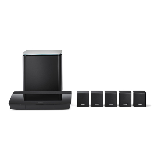
Bose LIFESTYLE 550 Service-Handbuch - Seite 2
Blättern Sie online oder laden Sie pdf Service-Handbuch für Home Theater System Bose LIFESTYLE 550 herunter. Bose LIFESTYLE 550 32 Seiten. Am/fm stereo receiver
Auch für Bose LIFESTYLE 550: Benutzerhandbuch (17 seiten), Benutzerhandbuch (44 seiten)

Safety Information ............................................................................................................................ 3
Electrostatic Discharge Sensitive (Esds) Device Handling ........................................................ 4
Specifications ................................................................................................................................ 5-6
Technical Description ...................................................................................................................... 7
Disassembly/Assembly Procedures ......................................................................................... 8-10
Figure 1. Antenna Placement Diagram .......................................................................................... 10
Test Procedures ........................................................................................................................ 11-14
Figure 2. AM/FM Adjustment Location ........................................................................................... 12
Figure 3. Amp Adjustment Location ............................................................................................... 14
Figure 4. Block Diagram ................................................................................................................. 15
Figure 5. Wiring Diagram ............................................................................................................... 16
Figure 6. Main PCB Layout ............................................................................................................ 17
Figure 7. PCB Layout ..................................................................................................................... 18
Figure 8. Exploded View ................................................................................................................ 19
Figure 9. Dial String Diagram ......................................................................................................... 20
Figure 10. Pinout Location Diagram ............................................................................................... 21
Part List Notes ................................................................................................................................ 22
Part List ...................................................................................................................................... 23-30
Voltage Conversion Instructions .................................................................................................. 31
Contents
2
