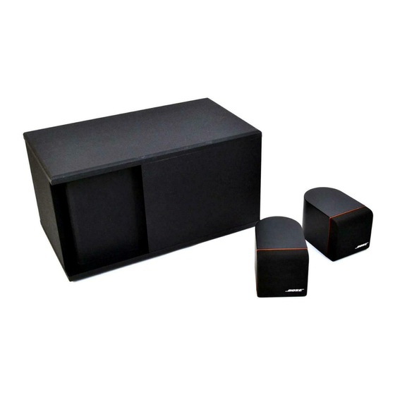
Bose Acoustimass 3 Series Handbuch - Seite 19
Blättern Sie online oder laden Sie pdf Handbuch für Stereo System Bose Acoustimass 3 Series herunter. Bose Acoustimass 3 Series 43 Seiten. Powered speaker system
Auch für Bose Acoustimass 3 Series: Benutzerhandbuch (17 seiten), Benutzerhandbuch (10 seiten), Service-Handbuch (42 seiten)

3. Tone Control Test
NOTE: This test can be performed with a fully
assembled module.
A. Connect an oscillator to the module's L/R
audio input terminals. Adjust the oscillator to 100
Hz, 220 mVrms.
B. Rotate the bass control knob fully clockwise
and counterclockwise from it's center or "normal"
position. The bass level should increase and
decrease cleanly without making a scratchy
noise. Clean or replace any potentiometer that
makes this noise.
C. Repeat this procedure for the treble control
using a frequency of 4 kHz.
4. Frequency Response of L/R (Twiddler)
Channels
NOTE: This test can be performed with a fully
assembled module.
A. Connect an oscillator to the module's L/R
audio input terminals. Adjust the oscillator to 1
kHz, 200 mVrms. Connect a piece of test
equipment capable of measuring decibels to
either the left or right twiddler output terminals
(labeled "To Cube Speakers"). Measure the dBs
at this setting and use this as a 0 dB reference.
B. Once the left or right output terminals of the
cube speaker are connected, adjust the oscillator
frequency and measure the relative response
according to the chart located at the end of this
procedure.
C. Repeat this test for the other channel.
Frequency
100 Hz
200 Hz
Relative Response
-15.6 dB ± 2.0 dB
+5.7 dB ± 1.5 dB
19
Frequency
360 Hz
1 kHz
2 kHz
10 kHz
20 kHz
5. Twiddler Power Output Test
NOTE: This test can be performed with a fully
assembled module.
Ω
A. Connect a 4
resistive load across the left or
right twiddler output terminal (labeled "To Cube
Speakers"). Connect a voltmeter across the
load.
NOTE: These measurements can be obtained at
120 and 240 V. Results will vary depending on
the line voltage used.
B. Connect an oscillator to the module's L/R
audio input terminals. Adjust the oscillator to 1
kHz, 454 mVrms.
C. Measure the voltage across the load. It should
be approximately 8.9 volts (20 watts). The
signal should look undistorted when viewed on
an oscilloscope.
6. Twiddler Short Circuit Protection Test
NOTES: This test can be performed with a fully
assembled module.
IMPORTANT: Do not short out for longer than 1
second.
A. Adjust the oscillator to 1 kHz, 200 mVrms.
Short the left or right twiddler output terminal.
The signal should mute for approximately 3
seconds.
Relative Response
-2.1 dB ± 1.5 dB
0 dB
-3.5 dB ± 1.5 dB
-.4 dB ± 1.5 dB
-2.9 dB ± 2.0 dB
