Bose Lifestyle Music Center Installationshandbuch - Seite 10

Blättern Sie online oder laden Sie pdf Installationshandbuch für Stereo System Bose Lifestyle Music Center herunter. Bose Lifestyle Music Center 38 Seiten. Home entertainment systems with vs-2 video enhancer
Auch für Bose Lifestyle Music Center: Betriebshandbuch (48 seiten), Betriebshandbuch (48 seiten), Benutzerhandbuch (19 seiten), Benutzerhandbuch (29 seiten), Installationshandbuch (44 seiten), Benutzerhandbuch (42 seiten), Informationen zur Einrichtung (1 seiten), Benutzerhandbuch (26 seiten), Erweiterung Manuallines (38 seiten), Betriebshandbuch (42 seiten), Betriebshandbuch (48 seiten), Betriebshandbuch (46 seiten), Benutzerhandbuch (12 seiten), Schnellstart-Handbuch (8 seiten), Installationshandbuch (30 seiten), Installationshandbuch (39 seiten)
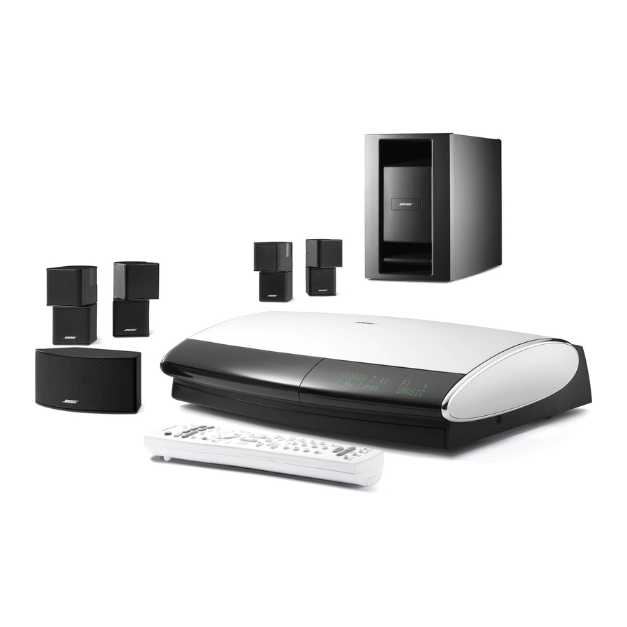
Bose Lifestyle Music Center Installationshandbuch
S
P
YSTEM
LACEMENT
Location choices for the Acoustimass module
Figure 5
Proper and improper posi-
tioning of an Acoustimass

module

10
Follow these guidelines for selecting a floor location (Figure 4), where the Acoustimass
module can be placed:
• Along the same wall as the TV, or the same end of the room as the front speakers.
• At least 18 inches (45 centimeters) from the TV to avoid magnetically interfering with the TV
image. Move it farther away if you still notice interference.
• Positioned with its grille (with a Bose logo) facing into the room or perpendicular to the
closest wall. This prevents the wall from blocking sound output or boosting the bass.
• Where it is not centered between two walls or between a floor and ceiling.
• Within reach of the audio input cable (30 feet or 9.1 meters); the five speaker cables
(20 feet or 6.1 meters for front and center speakers; 50 feet or 15.2 meters for surround
speakers), and your AC power (mains) outlet.
• Under a table or behind a cabinet, for convenience. However, NOT where furniture or
drapes block any openings on the module.
CAUTION: Do not block the ventilation slots for the built-in electronic circuitry in the module.
• On its two sides, its top, or its bottom, but NOT standing on either end (Figure 5).
Recommended
Top surface
Side surface
Not recommended
Front
Back
Ventilation
openings
• With four self-adhesive rubber feet attached to the surface that touches the floor, for
added stability and protection from scratches.
• Where it will not expose electronic media, like tapes, to its magnetic field for long periods.
Français
BEST
For best ventilation,
stand the module on
its bottom surface,
as shown, left.
ALTERNATE
Place the module
on one of its two
broad sides.
DO NOT
stand the module
on its slightly curved
back end, which can
cause it to tip over.
DO NOT
stand the module on
its front grille end. The
weight of the module
can damage the grille.
Español
English
®