Bose Lifestyle Music Center Installationshandbuch - Seite 15

Blättern Sie online oder laden Sie pdf Installationshandbuch für Stereo System Bose Lifestyle Music Center herunter. Bose Lifestyle Music Center 38 Seiten. Home entertainment systems with vs-2 video enhancer
Auch für Bose Lifestyle Music Center: Betriebshandbuch (48 seiten), Betriebshandbuch (48 seiten), Benutzerhandbuch (19 seiten), Benutzerhandbuch (29 seiten), Installationshandbuch (44 seiten), Benutzerhandbuch (42 seiten), Informationen zur Einrichtung (1 seiten), Benutzerhandbuch (26 seiten), Erweiterung Manuallines (38 seiten), Betriebshandbuch (42 seiten), Betriebshandbuch (48 seiten), Betriebshandbuch (46 seiten), Benutzerhandbuch (12 seiten), Schnellstart-Handbuch (8 seiten), Installationshandbuch (30 seiten), Installationshandbuch (39 seiten)
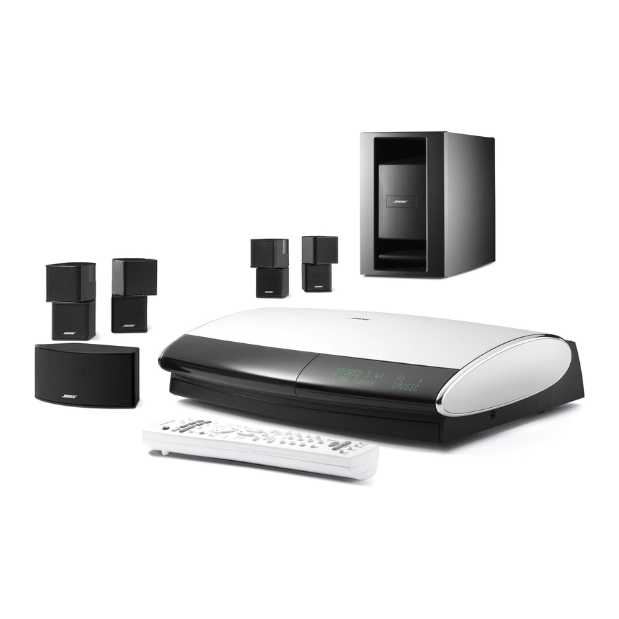
Bose Lifestyle Music Center Installationshandbuch
English
Español

Supplied and optional antennas

Figure 12
Connections for the AM
and FM antennas
Français
It may be convenient
1. Plug the small, round multi-pin connector (with the inset flat side up) at one end of the
cable into the Speakers jack labeled Main on the back of the media center.
2. Insert the telephone-type (RJ-45) connector on the other end into the Audio INPUT jack
on the Acoustimass
®
module. When properly inserted, it locks in place.
Be sure that each connector is fully inserted into each jack.
CAUTION: Do not put strain on the audio input cable, especially where it connects to the
module. Excessive strain can cause damage. Therefore, when disconnecting the cable from
the Acoustimass module, be sure to press the tab on the connector.
The supplied AM and FM antennas also connect to the rear panel of the media center
(Figure 12).
AM antenna lead
Note: The FM jack (75 ohm) may be used with an outdoor antenna. Before doing this, consult a
qualified installer. Follow all safety instructions supplied with the antenna.

FM antenna connection

1. Plug the connector on the FM dipole antenna lead into the FM antenna jack.
2. Spread out the antenna arms and change their orientation as needed to get the best FM
reception.
3. Place the antenna as far from the media center and other components as possible.
CAUTION: DO NOT try to connect television cable to the FM antenna jack.

AM antenna connection

1. Plug the connector on the AM antenna lead into the AM antenna jack.
2. Stand the loop antenna on the base or mount the antenna on a wall, following the
instructions enclosed with the AM antenna.
3. Move the AM loop antenna as far as possible (at least 20 inches or 50 centimeters) from
the media center, and at least 2 feet (60 centimeters) from the Acoustimass
When all connections are completed and you can turn on your system, you may need to
experiment with the orientation of the loop antenna for optimum AM reception.
Note: AM reception can be adversely affected by a nearby television, when it is on. Turn the TV
off for best AM reception.
B
ASIC
FM dipole antenna lead
Media center rear panel
S
C
YSTEM
ONNECTIONS
®
module.
15