Bose WAVE RADIO III Service-Handbuch - Seite 4
Blättern Sie online oder laden Sie pdf Service-Handbuch für Stereo System Bose WAVE RADIO III herunter. Bose WAVE RADIO III 10 Seiten. Owner's guide
Auch für Bose WAVE RADIO III: Benutzerhandbuch (28 seiten), Benutzerhandbuch (28 seiten), Benutzerhandbuch (24 seiten), Benutzerhandbuch (26 seiten), Benutzerhandbuch (28 seiten)
- 1. Table of Contents
- 2. Warranty Information
- 3. Specifications
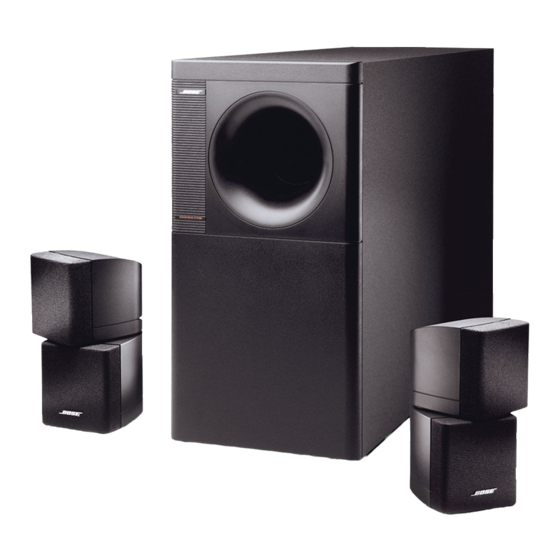
- 4. Product Description
- 5. Disassembly/Assembly Procedures
- 6. Test Procedures
- 7. Series III Test Setup Diagram
- 8. Part List Notes
- 9. Main Part List, Acoustimass 5 Series III (See Figure 2)
- 10. Packing List, Acoustimass 5 Series III Loudspeaker System (See Figure 3)
- 11. Part List, Acoustimass 5 Series III Loudspeaker System Crossover (See Figure 4)
DISASSEMBLY/ASSEMBLY PROCEDURES
Note: Refer to Figure 2 for the following
procedures.
1. Terminal Cap Removal
1.1 Using a phillips-head screwdriver,
remove the six screws (4) that secure the
terminal cap (7) to the bass module cabi-
net.
1.2 Gently pull the terminal cap away from
the cabinet. Be careful not to mark the
plastic of the terminal cap or chip the
wood of the bass module cabinet.
2. Terminal Cap Replacement
2.1 Place the terminal cap (7) onto the bass
module cabinet. Make sure it is fully seated
against the cabinet.
Note: Be sure the text on the label is
aligned with the text on the front of the
bass module.
2.2 Replace the six phillips-head screws (4)
removed in procedure 1.1. Do not
overtighten the screws.
3. Crossover Assembly Removal
3.1 Perform procedure 1.
3.2 Using a phillips-head screwdriver,
remove the four screws (9) that secure the
crossover assembly (8) to the terminal
cap (7).
3.3 Slide the crossover assembly off of the
tabs located on the terminal cap.
3.4 Cut the wires as close to the crossover
assembly as possible.
4. Crossover Assembly Replacement
4.1 Strip the wires from the woofer
assemblies (2) and solder them to the
appropriate locations on the crossover
assembly (8).
4.2 Slide the crossover assembly onto the
tabs located on the terminal cap (7).
4.3 Replace the four screws (9) removed
in procedure 3.2.
4.4 Perform procedure 2.
5. Woofer Assembly Removal
5.1 Perform procedure 1.
5.2 Using a phillips-head screwdriver,
remove the four screws (3) that secure the
woofer assembly (2) you wish to remove to
the cabinet.
5.3 Lift the woofer assembly out of the
cabinet and cut the wires as close to the
terminals as possible.
Note: Be sure to replace the woofer
gasket (1) when you replace the woofer
assembly.
6. Woofer Replacement
6.1 Strip the woofer cable wires.
6.2 Using a few small pieces of cellophane
tape, secure the new woofer gasket (1) to
the woofer assembly (2). This will hold it in
place while you install the woofer assembly
into the bass module cabinet.
6.3 Solder the woofer cable wires to the
woofer assembly. Refer to Figure 5.
6.4 Secure the woofer assembly in place
using the four screws (3) removed in
procedure 5.2.
6.5 Perform procedure 2.
4