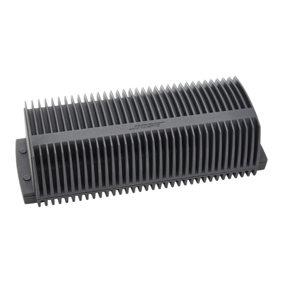
Bose Lifestyle 12 Benutzerhandbuch - Seite 15
Blättern Sie online oder laden Sie pdf Benutzerhandbuch für Verstärken Bose Lifestyle 12 herunter. Bose Lifestyle 12 22 Seiten. Bose lifestyle amplifier user's guide am262840
Auch für Bose Lifestyle 12: Benutzerhandbuch (34 seiten)

Connecting the Lifestyle
Figure 12
Cable connections between
the Model 5 music center
and the Lifestyle
®
stereo
amplifier
AM262840_00_V.pdf
stereo amplifier to a Model 5 music center
®
In systems using a Model 5 music center, home theater speakers are connected to the FIXED OUTPUT jacks
on the rear panel of the music center. When adding the Lifestyle
the theater speakers from the FIXED R and FIXED L OUTPUT jacks.
CAUTION: Before making connections, turn the Lifestyle
the AC (mains) power outlet. DO NOT plug the amplifier into an outlet until you have completed all other con-
nections.
CAUTION: DO NOT connect the audio input cable for the Lifestyle
SPEAKERS B outputs. The amplifier is designed to work properly with the fixed output level available from
the FIXED OUTPUT jacks.
1. Insert the single multi-pin connector at one end of the audio input cable into the multi-pin INPUT jack on
the rear of the amplifier (Figure 12).
2. At the other end of the audio input cable, insert the 3.5 mm mini-plug into the SYSTEM CONTROL 2 jack
on the rear panel of the music center.
3. On the rear panel of the music center, disconnect the audio input cables from both FIXED OUTPUT
jacks.
4. Insert the red RCA piggyback connector of the supplied cable into the R (right) FIXED OUTPUT jack.
Insert the white RCA piggyback connector into the L (left) FIXED OUTPUT jack.
5. Insert the red RCA connector of the Acoustimass
white RCA connector into the white piggyback jack.
Model 5 music center rear panel
L
FIXED
R
A
B
REC
PLAY
SPEAKERS
TAPE
OUTPUT
Fixed speaker outputs
January 4, 2002
Setting Up Your Lifestyle
®
system off and disconnect the music center from
®
module cable into the red piggyback jack and the
®
Lifestyle
3.5 mm mini-plug
AM LOOP
1
L
SYSTEM
CONTROL
R
2
VIDEO
AUX
SOUND
INPUT
ANTENNA
SEE INSTRUCTION MANUAL
®
Stereo Amplifier
®
amplifier, you need to temporarily unplug
®
stereo amplifier to the SPEAKERS A or
stereo amplifier rear panel
4
MINIMUM
L
L
SYSTEM
R
CONTROL
R
+
–
SPEAKER OUTPUTS
INPUT
SPEAKER OUTPUTS
POWER
~
12VAC
IN
1.0A
30-ft audio input
cable (supplied)
Acoustimass module
cable
L
L
R
R
13
